| CPC B64C 27/473 (2013.01) [B64D 15/12 (2013.01); B64D 45/00 (2013.01); F16C 19/06 (2013.01); H01F 21/04 (2013.01); B64C 27/06 (2013.01); F16C 2326/43 (2013.01)] | 44 Claims |

|
1. A rotor (3, 4) for a hover-capable aircraft (1), comprising:
a support (9) angularly fixed with respect to an axis (B, C) and housing an electrical power source (20);
a unit (11, 12) rotatable with respect to said support (9) about said axis (B, C) and housing an electrical load (21, 24) of the resistive type; and
a power supply system (19, 19′, 19″, 19″′, 19″″, 19″″′, 19″″″, 19″″″′) adapted to electrically power said electrical load (21, 24); said power supply system (19, 19′, 19″, 19″′, 19″″, 19″″′, 19″″″, 19″″″′), in turn, comprising:
at least a first rotary transformer (22) electrically interposed between said power source (20) and said electrical load (21, 24); said first rotary transformer (22), in turn, comprising:
a first winding (26) arranged on said support (9), electrically connected to said power source (20) and which can be electrically supplied with an alternating voltage at a frequency value;
a second winding (28) arranged on said unit (11, 12, 13), electromagnetically coupled to said first winding (26) and electrically connected to said electrical load (21, 24);
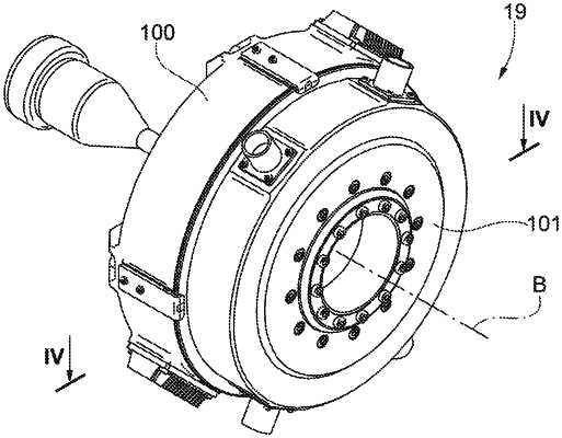
a stator (100) carried by said support (9), rotationally fixed with respect to said axis (B, C) and to which said first winding (26) is fixed; and
a rotor (101) operatively connected to said unit (11, 12) and to which said second winding (28) is fixed;
said power supply system (19, 19′, 19″, 19″′, 19″″, 19″″′, 19″″″, 19″″″′) comprising a capacitive circuit (50) electrically connected to said first rotary transformer (22), so as to reduce the reactive power absorbed by said first rotary transformer (22); characterized in that said stator (100) defines a seat (171) engaged by an appendage (140) of said rotor (101); said seat (171) being engaged with axial play by said appendage (140) when said rotor (101) is correctly positioned with respect to said stator (100); said seat (171) making axial contact with said appendage (140) when said stator (100) is positioned incorrectly in the axial direction.
|