| CPC B63B 35/44 (2013.01) [H01Q 1/04 (2013.01); H01Q 1/30 (2013.01); H01Q 1/34 (2013.01); H01Q 9/36 (2013.01); B63B 2035/442 (2013.01)] | 12 Claims |

|
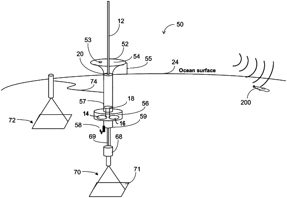
1. A spar buoy for very low frequency (VLF) or low frequency (LF) transmission comprising:
a first portion of the spar buoy extending above a mean water line comprising:
a conductive structure comprising a coaxial feed; and
an antenna coupled to the coaxial feed and extending above the conductive structure; and
a second portion of the spar buoy below the mean water line comprising:
a transmitter coupled to the coaxial feed; an energy storage subsystem coupled to the transmitter; and
an electric power generation subsystem coupled to the energy storage subsystem;
wherein the conductive structure comprises:
a horn flaring upward toward the antenna,
a nonconductive sealing cap over the horn to contain a gas or a liquid within the horn; and
a device on the nonconductive sealing cap for filling or evacuating the gas or liquid;
wherein the gas comprises an inert gas, SF6, dry N2, or a vacuum; and
wherein the liquid comprises a dielectric liquid, silicone oil, or mineral oil.
|