| CPC B60C 9/0292 (2013.01) [B60C 3/00 (2013.01); B60C 15/0607 (2013.01); B60C 15/0018 (2013.01); B60C 15/0036 (2013.01); B60C 2015/061 (2013.01); B60C 2015/0621 (2013.01); Y10T 152/10837 (2015.01)] | 14 Claims |

|
1. A light truck pneumatic radial tire comprising:
a tread portion;
a pair of sidewall portions;
a pair of bead cores;
a carcass layer comprising at least one carcass ply extending between the pair of bead cores through the tread portion and the pair of sidewall portions;
a pair of first bead apex rubber components each disposed outward in a tire radial direction of a respective one of the pair of bead cores; and
a belt layer disposed outward in the tire radial direction of the carcass layer,
wherein
the light truck pneumatic radial tire has a standard internal pressure of 350 to 600 kPa,
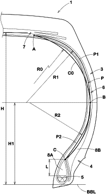
in an unloaded condition where the tire is mounted onto a standard wheel rim and inflated with an internal pressure at 50 kPa, the carcass layer has a profile in cross-section on each axial side of the tire that comprises an outer side portion, the outer side portion extending from an axial position A where the carcass layer separates from the belt layer near an outer end of the belt layer in the tire axial direction to a maximum width position B of the carcass layer profile,
the respective outer side portion is located outside a virtual arc C0 having a single radius R0 of curvature passing through the position A, the maximum width position B, and an axial position C of an outermost end in the tire radial direction of a respective one of the pair of first bead apex rubber components, and
a distance H1 in the tire radial direction from a bead baseline to the respective maximum width position B is in a range from 0.40 to 0.50 times a maximum distance in the tire radial direction from the bead baseline to the profile.
|