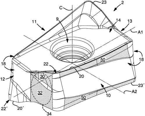
| CPC B23C 5/202 (2013.01) | 22 Claims |

|
1. A cutting insert for a milling tool, the cutting insert comprising:
a first side defining a first extension plane;
a second side opposite the first side, the second side defining a second extension plane, wherein a centre axis extends perpendicularly through the first and second extension planes;
a circumferential surface extending between the first side and the second side, the circumferential surface including a first pair of opposing side surfaces and a second pair of opposing side surfaces;
a median plane extending halfway between the first extension plane and the second extension plane;
a longitudinal plane extending halfway between the first pair of opposing side surfaces, perpendicularly to the median plane and containing the centre axis;
a central plane extending perpendicularly to both the median plane and the longitudinal plane and containing the centre axis;
a first axis extending along an intersection between the median plane and the longitudinal plane and a second axis extending along an intersection between the median plane and the central plane;
a first cutting edge extending along an intersection between the first side and the circumferential surface on a first side of the longitudinal plane, the first cutting edge, as seen in a view towards the first side, extending along a first corner of the cutting insert; and
a second cutting edge extending along an intersection between the second side and the circumferential surface on a second side of the longitudinal plane, the second cutting edge, as seen in a view towards the second side, extending along a second corner of the cutting insert, wherein
the first cutting edge includes a first main cutting edge, a first corner cutting edge, and a first auxiliary cutting edge, the first auxiliary cutting edge having a first surface-wiping secondary cutting edge, wherein the first main cutting edge adjoins the first corner cutting edge, and the first corner cutting edge adjoins the first surface-wiping secondary cutting edge, wherein
the second cutting edge includes a second main cutting edge, a second corner cutting edge, and a second auxiliary cutting edge, the second auxiliary cutting edge having a second surface-wiping secondary cutting edge, wherein the second main cutting edge adjoins the second corner cutting edge, and the second corner cutting edge adjoins the second surface-wiping secondary cutting edge, and
as seen in a direction along the first axis, a first axial relief face adjacent to the first auxiliary cutting edge and a first axial abutment face form part of a first surface grouping on the first side of the longitudinal plane, and a second axial relief face adjacent to the second auxiliary cutting edge and a second axial abutment face form part of a second surface grouping on the second side of the longitudinal plane, wherein
the first axial relief face includes a first part of the first axial relief face adjacent to the first surface-wiping secondary cutting edge, and the second axial relief face includes a first part of the second axial relief face adjacent to the second surface-wiping secondary cutting edge, at least the first part of the first axial relief face forming an obtuse first inner angle with the median plane when seen in a section parallel to the longitudinal plane, and at least the first part of second axial relief face forming an obtuse second inner angle with the median plane when seen in a section parallel to the longitudinal plane, wherein
the first surface grouping and the second surface grouping form part of the circumferential surface, wherein
the insert has 180° rotational symmetry with respect to rotation about the second axis and/or the first axis and/or the centre axis, wherein
as measured in a direction in parallel with the longitudinal plane, in a section of the median plane through the cutting insert, the cutting insert is longest along the longitudinal plane, wherein
as seen in a direction along the second axis, each point of the first surface grouping has a unique projection point on the longitudinal plane, and wherein
as seen in a direction along the second axis in an opposite direction, each point of the second surface grouping has a unique projection point on the longitudinal plane, wherein
the first surface grouping and the second surface grouping meet in a partitioning line, wherein the partitioning line extends in the longitudinal plane from the first side to the second side.
|