| CPC A63B 21/0616 (2015.10) [A63B 17/00 (2013.01); A63B 21/06 (2013.01); A63B 21/0615 (2013.01); A63B 21/0626 (2015.10); A63B 21/0628 (2015.10); A63B 21/078 (2013.01); A63B 21/08 (2013.01); A63B 21/16 (2013.01); A63B 21/4035 (2015.10); A63B 23/035 (2013.01); A63B 23/03508 (2013.01); A63B 21/055 (2013.01); A63B 21/0552 (2013.01); A63B 21/065 (2013.01); A63B 21/0724 (2013.01); A63B 21/0783 (2015.10); A63B 23/03541 (2013.01); A63B 23/03558 (2013.01); A63B 23/04 (2013.01); A63B 2023/0411 (2013.01); A63B 2225/093 (2013.01)] | 30 Claims |

|
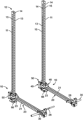
1. An adjustable carriage assembly comprising:
a carriage defining a passage configured to receive a frame member therethrough such that the carriage is moveable along the frame member, wherein the carriage comprises a first side plate and a second side plate laterally spaced from the first side plate, wherein the passage is defined between the first and second side plates, wherein the carriage further comprises a rear plate extending between the first and second side plates at a rear of the carriage;
a plurality of rollers rotatably connected to the first and second side plates and extending between the first and second side plates, the plurality of rollers comprising a first roller located on a front side of the passage, a second roller located below the first roller on the front side of the passage, a third roller spaced rearwardly from the first roller and located on a rear side of the passage, and a fourth roller spaced rearwardly from the second roller and located below the third roller on the rear side of the passage, such that the first and second rollers are configured to engage a front side of the frame member and the third and fourth rollers are configured to engage a rear side of the frame member, wherein each of the plurality of rollers comprises:
a first enlarged end section and a second enlarged end section opposite the first enlarged end section;
a first intermediate section and a second intermediate section extending inwardly from the first and second enlarged end sections, the first and second intermediate sections having gradually decreasing diameters; and
a central cylindrical section located between the first and second intermediate sections and forming a center portion of the roller, wherein the central cylindrical section has a diameter that is smaller than the diameters of the first and second enlarged end sections;
a connection structure connected to the first and second side plates of the carriage at a front of the carriage, wherein the connection structure is configured for pivotable connection to an articulating implement; and
a releasable pin mounted on the carriage proximate to the rear of the carriage and positioned midway between the first and second side plates, wherein the releasable pin is mounted on the rear plate and extends through the rear plate, the releasable pin comprising an arm extending outward from the releasable pin and a distal end distal from the arm, wherein the releasable pin is moveable by axial translation between a locked position, where the distal end of the releasable pin extends into the passage and is configured to be received in a hole in the frame member to lock the carriage in position, and an unlocked position, where the distal end of the releasable pin is retracted with respect to the locked position and is configured to withdraw from the hole in the frame member to allow movement of the carriage with respect to the frame member, and wherein the arm is configured for engagement to move the releasable pin from the locked position to the unlocked position.
|