| CPC A46B 9/04 (2013.01) [A46B 1/00 (2013.01); A46B 3/00 (2013.01); A46B 3/005 (2013.01); A46B 3/04 (2013.01); A46B 3/12 (2013.01); A46D 1/0207 (2013.01); A46D 1/0238 (2013.01); A46D 1/0269 (2013.01); A46D 1/0276 (2013.01); A46D 3/00 (2013.01); A46D 3/005 (2013.01); B29C 33/301 (2013.01); B29C 45/0055 (2013.01); B29C 45/14385 (2013.01); B29C 45/2626 (2013.01); B29C 45/34 (2013.01); B29C 45/561 (2013.01); A46B 2200/1066 (2013.01); B29C 45/2673 (2013.01); B29L 2031/425 (2013.01)] | 15 Claims |

|
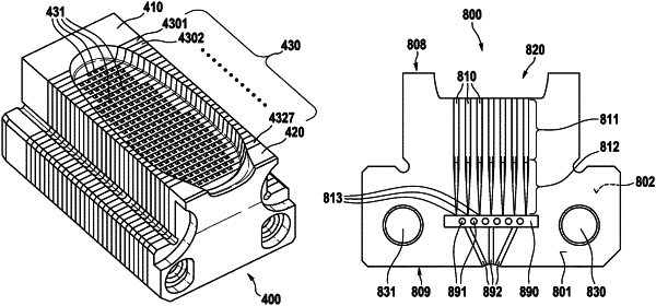
1. A mold insert defining at least one filament cavity and comprising a stack of at least a first insert plate and a second insert plate, wherein
the first insert plate has a top surface, a bottom surface opposite to the top surface, and a front face extending between the top and bottom surfaces, and closely abutting a front face of the second insert plate;
at least a portion of the at least one filament cavity is provided in at least one of the front faces of the first insert plate and the second insert plate such that the filament cavity is open at a top surface of the mold insert and terminates with a blind-hole at a bottom surface thereof so that the at least one filament cavity does not extend through the bottom surface;
a venting cavity is provided in the front face of the insert plate in which the portion of the at least one filament cavity is provided, which venting cavity is in air-conducting connection with the blind-hole end of the filament cavity;
at least one venting channel connecting the venting cavity to an area outside the insert plates; and
the venting cavity has a depth extending in a direction perpendicular to the front face of the respective first or second insert plate in which the venting cavity is provided, the venting cavity being in air-conducting connection with the blind-hole, wherein the venting cavity comprises at least one stopper element provided to prevent deformation of the insert plates during molding when the insert plates are under pressure.
|