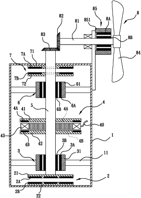
| CPC H02K 7/09 (2013.01) [F03D 9/25 (2016.05); H02K 7/116 (2013.01); H02K 7/183 (2013.01); F05B 2220/706 (2013.01)] | 4 Claims |

|
1. A wind-powered maglev generator assembly, comprising:
a hollow casing, the hollow casing comprising a bottom inner wall, a top inner wall, and opposing side walls;
a lower magnetic repulsion support on the bottom inner wall of the casing;
an upper magnetic repulsion support on the top inner wall of the casing;
a plurality of magnetic bearings positioned inside the casing between the lower support and the upper support, each magnetic bearing connected to the opposing side walls by a rack assembly;
a main axle running vertically through the magnetic bearings, where a bottom end of the main axle is joined to the lower support and a top end of the main axle extends outside the casing through the upper support;
a generator comprising a stator and a rotor, the stator comprising a plurality of coils, the rotor comprising at least one rotating disc, the disc having an inner side facing the stator coils,
wherein the coils are fixedly surrounding the main axle and connected to a power transmission cable, the at least one rotating disc is fixed to the main axle, and a plurality of inductive magnets are arranged on the inner side of the at least one rotating disc and mounted opposite to the coils; and
a fan unit mounted on an outer side of the casing and coupled to the main axle;
wherein, when the fan unit spins due to an oncoming wind flow, the main axle is driven by the fan unit to spin, and the at least one rotating disc of the generator rotates relative to the coils; and electrical current is induced in the coils and output from the transmission cable; and
wherein:
the lower support comprises a circular lower rotating disc and a circular lower fixed disc; the lower rotating disc comprises a plurality of first magnets; the circular lower fixed disc comprises a plurality of second magnets; the first magnets are arranged on a lower side of the circular lower rotating disc and mounted around a center of the circular lower rotating disc; a center of an upper side of the circular lower rotating disc is fixed to a lower end of the main axle; the second magnets are arranged on an upper side of the circular lower fixed disc and mounted around a center of the lower fixed disc; the circular lower fixed disc is fixed to a lower inner wall of the casing and mounted opposite to the circular lower rotating disc;
the upper support comprises a circular upper fixed disc and a circular upper rotating disc; the circular upper fixed disc comprises a plurality of third magnets and the circular upper rotating disc comprises a plurality of fourth magnets; the third magnets are arranged on a lower side of the circular upper fixed disc and mounted around a center of the circular upper fixed disc; the fourth magnets are arranged on an upper side of the circular upper rotating disc and mounted around a center of the upper rotating disc; an upper side of the circular upper fixed disc is fixed to an upper inner wall of the casing; the circular upper rotating disc is fixed to the main axle and mounted opposite to the circular upper fixed disc; and
the first magnets and the second magnets are of a same magnetic polarity; the third magnets and the fourth magnets are of a same magnetic polarity; and, due to repulsion between the first and second magnets, and repulsion between the third and fourth magnets, the upper rotating and fixed discs do not contact each other and the lower rotating and fixed discs do not contact each other.
|