| CPC H02J 3/001 (2020.01) [H02J 2203/20 (2020.01)] | 1 Claim |

|
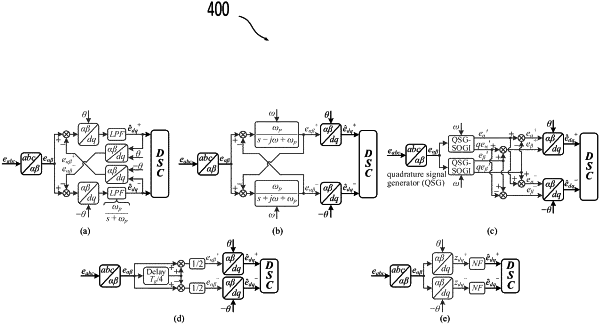
1. A method for controlling an inverter-interfaced renewable energy source (IIRES), wherein the IIRES includes a converter, a decoupled sequence control (DSC) system and a power filter, and the DSC system includes a current controller, a low-voltage ride-through (LVRT) control unit, and a positive and negative sequence components calculation (PNSCC) structure including a dual synchronous reference frame (DSRF)-based PNSCC structure, a dual complex-coefficient filter (DCCF)-based PNSCC structure; a dual second-order generalized integrator (DSOGI)-based PNSCC structure, a delayed signal cancellation (dsc)-based PNSCC structure, and a notch filter (NF)-based PNSCC structure, the method comprising:
determining the PNSCC structures in a synchronous reference frame (SRF), as
 where s is a Laplace operator, Xdq(s)=[Xd+(s), Xd−(s), Xq−(s), Xq−(s)]T denotes a value of the grid current, an inverter output voltage or a terminal voltage, Xdq(s)=[Xd+(s), Xq+(s), Xd−(s), Xq−(s)]T represents an estimated value of Xdq(s), which is extracted by the PNSCC, Hφ(s) is an objective transfer function of PNSCC, H11˜H44 are elements of Hφ(s) H22=H33=H44=H11, H21=H34=−H43=−H12, H31=H42=H24=H13, and H41=−H32=−H23=H14, and superscript φ∈{DSRF, DCCF, DSOGI, dsc, NF};
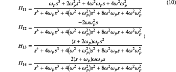
determining transfer function HDSRF(s)=HDCCF(s) for the DSRF-based PNSCC structure and the DCCF-based PNSCC structure, as
 where ωp is a cutoff frequency of an adopted low-pass filter in the DSRF- or DCCF-based PNSCC, and ω=100π;
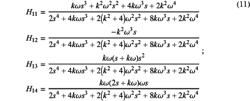
determining transfer function HDSOGI(s) for the DSOGI-based PNSCC structure, as
 where k is a constant parameter used in DSOGI:
determining transfer function Hdsc(s) for the dsc-based PNSCC structure, as
 where T=Tg/4 and Tg is a time cycle of the grid voltage;
determining transfer function HNF(s) for the NF-based PNSCC structure, as
 where NF(s) denotes a transfer function of a notch filter, and NF(s)=(s2+ωNF2)/(s2+2kNFωNFS+ωNF2), kNF and ωNF are constant parameters used in the notch filter;
determining from the equations (4), (10), (11), (13) and (15) a fault equation of the IIRES with the DSC, as
Idq(s)=Gm−1(s)(PI(s)JIdq*(s)+(Hφ(s)−J)Edq(s)) (18);
where Idq(s), Idq*(s) and Edq(s) denote a grid current equation, a grid current reference equation and a terminal voltage equation in a frequency domain, respectively, PI(s) is a transfer function of a proportional-integral controller, PI(s)=(kp+ki/s), kp and ki are a proportional gain and an integral gain, Gm(s) is a 4×4 matrix covering G11˜G44, G11=PI(s)H11+Pd(s)+ωLH21, G12=PI(s)H12+ωL(H22−1), G13=PI(s)H13+ωLH23, G14=PI(s)H14+ωLH24, and G22=G33=G44=G11, G21=G34=−G43=−G12, G31=G42=G24=G13, and G41=−G32=−G23=G14, Pd(s) is a damping term attributed to a power filter and Pd(s)=(Ls+R), R and L are total resistance and total inductance of the power filter, J is an identity matrix;
using the transfer functions HDSRF(s), HDCCF(s), HDSOGI(s), Hdsc(s) and HNF(s), determining from the equation (4) an equation of the PNSCC structures in the SRF, as
 where a cutoff frequency ωf depends on a type of the PNSCC structure;
from the equations (18) and (23) and by using an inverse Laplace transform, determining a fault equation of the IIRES with the DSC in a fault detection phase, as
 where idFD+(t) is a time-domain positive-sequence grid current equation in a fault detection phase, 1/τ=R/L, ωn=(ωcωf)1/2, ζ=ωn/(2ωc), M=(1−ζ2)1/2, 1/A=(ωn−τ)2+M2, and ωc is an open-loop cutoff frequency of a current control loop, ωc=kp/L=ki/R, φ1 is an initial phase angle of idFD+(t), t0 is a fault time, and tc is an end time of the fault detection phase;
from the equations (18) and (23) and by using an inverse Laplace transform, determining a fault equation of the IIRES with the DSC in a control transient response (CTR) phase, as
 where idCTR+(t) is a time-domain positive-sequence grid current equation in a control transient response phase, φ2 is an initial phase angle of idCTR+(t), and tf is a start time of a fault steady phase;
detecting a short-circuit fault by the converter and analyzing the short-circuit fault using the equation (25);
switching the DSC system from a first mode to a current control mode through the LVRT unit by the current controller, and analyzing the short-circuit fault using the equation (27); and
suppressing an inrush current to protect the IIRES, wherein the inrush current is a maximum fault current with a peak value exceeding Ilim, which is caused by the existence of PNSCC structure as determined by equation (23) and an fault detection phase.
|