| CPC H02B 1/46 (2013.01) [H02B 1/20 (2013.01); H02B 1/38 (2013.01)] | 3 Claims |

|
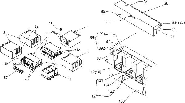
1. A power distribution device for a distribution board, the power distribution device comprising:
a housing including an upper housing configured to protect an upper portion of the power distribution device for the distribution board, and a lower housing configured to support and protect a lower portion of the power distribution device for the distribution board;
a connection module disposed in a space in the housing and integrated with connection terminals to receive power of a main circuit breaker and a branch circuit breaker; and
the connection terminal fastened to the connection module and configured to distribute power,
wherein the connection module comprises:
the connection terminal having first and second ends and a plate-shaped surface having a predetermined width and extending in a length direction between the first and second ends, the plate-shaped surface, between the first and second ends, having rivet coupling holes and connection holes;
a connection member including first and second connection members coupled to cover the second end of the connection terminal in an upward/downward direction so that the second end has a connecting and electrically conducting connection hole, the first and second connection members having two opposite edges corresponding to each other, open ends having the connection holes, fastening holes, and coupling holes;
coupling members configured to fix and penetrate the coupling holes of the connection member and the rivet coupling holes of the connection terminal;
an electrically conducting fastening member fastened while penetrating the connection hole of the second end and the upper and lower fastening holes and configured to allow the second end of the connection terminal to be inserted into the connection hole; and
a ring-shaped nut member fixed to a fastening groove portion of the lower housing so that the electrically conducting fastening member is fastened and fixed to the ring-shaped nut member while penetrating the fastening holes and the connection hole.
|