| CPC H01M 10/0525 (2013.01) [H01M 4/133 (2013.01); H01M 4/134 (2013.01); H01M 4/386 (2013.01); H01M 4/525 (2013.01); H01M 4/587 (2013.01); H01M 4/667 (2013.01); H01M 4/70 (2013.01); H01M 10/0436 (2013.01); H01M 10/052 (2013.01); H01M 10/058 (2013.01)] | 17 Claims |

|
1. A secondary battery comprising a sealed battery enclosure, an electrode structure, a negative electrode tab, and a positive electrode tab, wherein
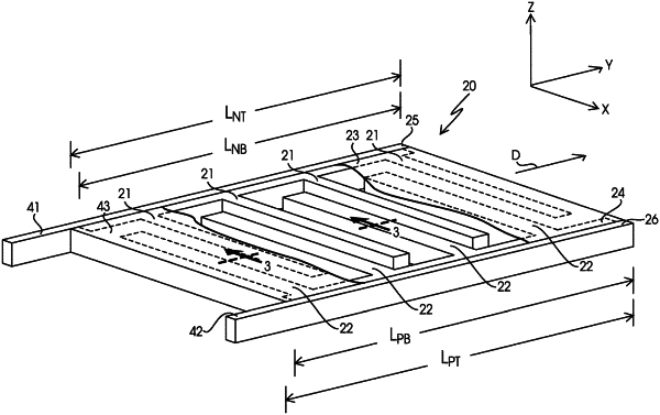
the electrode structure comprises a population of negative electrodes, a negative electrode bus, a population of positive electrodes, and a positive electrode bus, the populations of negative and positive electrodes being arranged in an alternating sequence in which members of the negative electrode population are separated from each other by members of the positive electrode population with the alternating sequence proceeding in a first direction, each member of the negative electrode population comprising a negative electrode active material layer and a negative electrode current collector layer having lateral surfaces, each member of the negative electrode population having a bottom, a top, a length LE, a width WE and a height HE, the length LE being measured from the bottom to the top of each such electrode, the width WE and the height HE being measured in directions that are perpendicular to each other and to the direction of measurement of the length LE, the ratio of LE to each of WE and HE being at least 5:1, respectively, the ratio of HE to WE being between 0.4:1 and 1000:1, respectively, wherein (i) the negative electrode active material layer is disposed on each of the lateral surfaces of the negative electrode current collector layer in members of the negative electrode population, (ii) the negative electrode current collector layer of each member of the negative electrode population has a length LE-C that is measured in the same direction as and is at least 50% of length LE, (iii) the negative electrode current collector layer of each member of the negative electrode population is electrically connected to and extends from the negative electrode bus which, in turn, is electrically connected to the negative electrode tab, and which pools current from all of the members of the negative electrode population and provides an electrically conductive pathway between each individual member of the negative electrode population and the negative electrode tab, (iv) the negative electrode bus has a length LE-B, a width WE-B and a height HE-B, the length LE-B being measured in the first direction and the width WE-B and the height HE-B being measured in directions that are mutually perpendicular to each other and perpendicular to the first direction with the ratio of LE-B to each of WE-B and HE-B being at least 5:1, and (v) the negative electrode population has N members, the positive electrode population has N+1 members, and N is at least 10, and
the negative electrode tab extends from inside the sealed battery enclosure to outside the sealed battery enclosure at a first side of the electrode structure to provide an electrical connection between the electrode structure and an external energy supply, and the positive electrode tab extends from inside the sealed battery enclosure to outside the sealed battery enclosure at a second side of the electrode structure that is opposite the first side, to provide an electrical connection between the electrode structure and an external energy supply.
|