| CPC G03G 21/0052 (2013.01) [G03G 7/0013 (2013.01); G03G 15/0808 (2013.01); G03G 15/081 (2013.01); G03G 15/0889 (2013.01); G03G 21/206 (2013.01); G03G 2215/085 (2013.01); G03G 2221/0021 (2013.01)] | 6 Claims |

|
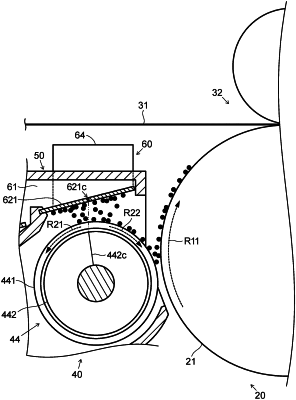
1. An image forming apparatus, comprising:
an image bearing member that has an outer peripheral surface on which an electrostatic latent image is formed;
a charging unit that is configured to charge the outer peripheral surface of the image bearing member;
a cleaning unit that is configured to clean the outer peripheral surface of the image bearing member;
a developing device including
a developing container that is configured to contain developer which contains toner to be supplied to the image bearing member,
a developer conveying member
that is supported in a conveying chamber of the developing container in a manner that allows the developer conveying member to rotate, and
that is configured to circulate the developer by stirring and conveying the developer, and
a developer carrying member
that is supported in the developing container in a manner that allows the developer carrying member to rotate while the developer carrying member faces the image bearing member, and
that is configured to supply the toner in the conveying chamber to the image bearing member;
a voltage application section that is configured to apply developing voltage to the developer carrying member; and
a control section that is configured to control
the image bearing member,
the charging unit,
the cleaning unit,
the developing device, and
the voltage application section,
the developing device including
a toner trapping mechanism which includes
a duct
that is connected to the conveying chamber, and
that is configured to allow air in the conveying chamber to flow through the duct,
a filter
that is arranged at a portion where the duct and the conveying chamber are connected to each other above the developer carrying member, and
that is configured to trap the toner which flows from the conveying chamber into the duct,
an exhaust fan that is configured to cause the air in the conveying chamber to flow out to an outside through the duct, and
a vibration generating unit that is configured to vibrate the filter,
the control section being capable of carrying out a scattered-toner recovery mode in which, while image formation is prevented from being performed, scattered toner that has dropped from the filter and adhered to an outer peripheral surface of the developer carrying member is recovered by the cleaning unit through intermediation of the image bearing member
by causing, by the control section, the vibration generating unit to vibrate the filter,
by causing, by the control section, the charging unit and the voltage application section to cause a potential difference in a direction in which the toner is moved from the developer carrying member to the image bearing member,
by causing, by the control section, the developer carrying member to rotate in a direction reverse to a direction at a time of the image formation, and
by causing, by the control section, the image bearing member to rotate in a same direction as a direction at the time of the image formation,
the developer carrying member including
a developing sleeve
that has a hollow cylindrical shape,
that is rotatable, and
that is configured to carry the developer on an outer peripheral surface of the developing sleeve,
a fixed magnet
that is fixed in the developing sleeve in a manner that prevents the fixed magnet from rotating, and
that has a plurality of magnetic poles which are arrayed along a circumferential direction of the developing sleeve,
an absolute value of a perpendicular-magnetic-force gradient of the fixed magnet being 4.0 mT/° or less at a position where the fixed magnet faces a central portion of the filter in a rotation direction of the developing sleeve.
|