| CPC G03B 35/04 (2013.01) [G02B 26/0816 (2013.01); H04N 13/239 (2018.05); H04N 13/271 (2018.05); H04N 23/51 (2023.01); H04N 23/55 (2023.01); H04N 23/56 (2023.01); H04N 23/67 (2023.01)] | 21 Claims |

|
1. A device comprising:
a housing having two oppositely located main sides which are connected to each other via at least one edge side;
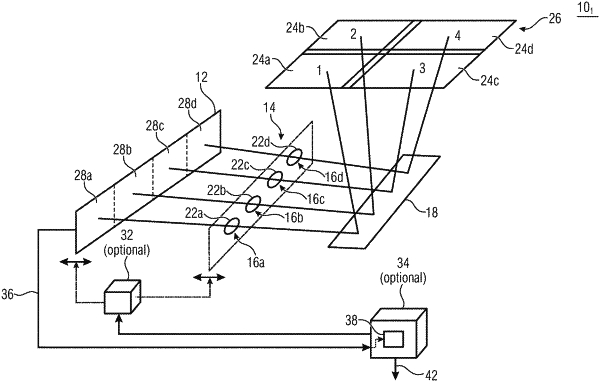
a multi-aperture imaging device arranged in an interior of the housing and comprising:
an image sensor arrangement;
an array of adjacently arranged optical channels, each optical channel including an optic for projecting at least one partial field of view of a total field of view onto an image sensor area of the image sensor arrangement, and
a beam deflection means for deflecting an optical path of the optical channels, the beam deflection means comprising a plurality of facets, each optical channel having a facet associated with it;
wherein one of the main sides comprises a passage area arrangement with at least one passage area, the passage area arrangement being set up to allow the optical paths to pass;
wherein the optical channels comprise, in relation to the passage area arrangement and along an axial direction, along a course of the optical path of the optical channels between the image sensor arrangement and the beam deflection means, a channel-specific relative position of at least one of:
the image sensor area;
the optic;
a reflecting surface of a facet associated with the optical channel as a distance between the reflecting surface of the facet and the optic of the optical channel, differing from another optical channel;
wherein the passage area arrangement causes, as compared to a relative position that is global to all the channels, a reduction of a required size of the passage area arrangement along the axial direction, which nevertheless enables unimpeded passage of the optical paths: or
wherein the channel-specific relative position causes, as compared to a relative position that is global to all the channels, an increase in the overlap of projections of beams of rays of the optical paths within an area of the passage area arrangement, and a size of the passage area arrangement is adapted to the increase in overlap, the projections being projected along a line extension direction of the array.
|