| CPC G03B 3/10 (2013.01) [G03B 13/36 (2013.01)] | 6 Claims |

|
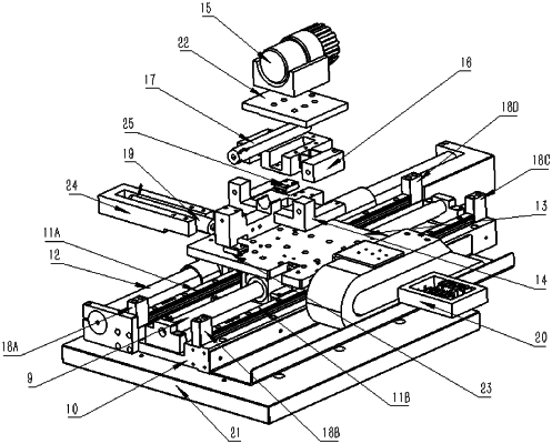
1. A macro-to-micro two-stage camera lens focusing device based on a direct-drive air floatation platform, configured to be mounted on a y axis (2) of an aerostatic air flotation platform and comprising:
a base (10), configured to be disposed on the y axis (2) of the aerostatic air flotation platform;
a z-direction macro-motion system, disposed on the base (10), wherein the z-direction macro-motion system is configured to realize macro-motion focusing of an industrial camera lens (15) along a z direction;
a micro-motion focusing system, comprising: a z-direction micro-motion focusing system and a y-direction micro-motion focusing system; wherein the z-direction micro-motion focusing system is disposed above the z-direction macro-motion system, and the y-direction micro-motion focusing system is disposed above the z-direction micro-motion focusing system; each of the z-direction micro-motion focusing system and the y-direction micro-motion focusing system adopts a structure combining rigid arms and flexible arms; and the z-direction micro-motion focusing system and the y-direction micro-motion focusing system are configured to realize micro-motion focusing along the z direction and a y direction, respectively;
wherein the z-direction micro-motion focusing system comprises:
a micro-motion platform (13), slidably connected to the base (10);
a micro-motion platform base (14), fixedly connected to the micro-motion platform (13);
a z-direction micro-motion flexure hinge (16), fixedly disposed on the micro-motion platform base (14);
a z-direction piezoceramic actuator (17), fixedly disposed in the micro-motion platform base (14) and the z-direction micro-motion flexure hinge (16); wherein a top portion of the z-direction piezoceramic actuator (17) is configured to push the z-direction micro-motion flexure hinge (16) to perform nanoscale motion through a piezoelectric effect, thereby completing the micro-motion focusing along the z direction; and
the industrial camera lens (15), disposed on the z-direction micro-motion flexure hinge (16);
wherein the y-direction micro-motion focusing system comprises:
a y-direction micro-motion flexure hinge (20), fixedly disposed on the micro-motion platform (13) and fixedly connected to the micro-motion platform base (14);
a y-direction piezoceramic mounting base (24), fixedly disposed on the micro-motion platform (13);
a y-direction piezoceramic actuator (19), fixedly disposed in the y-direction piezoceramic mounting base (24); wherein the y-direction piezoceramic actuator (19) is configured to make the micro-motion platform base (14) generate a micro displacement along the y direction by pushing a side of the micro-motion platform base (14), thereby causing the industrial camera lens (15) disposed on the micro-motion platform base (14) to produce the micro-motion focusing along the y direction; and
two y-direction micro-motion guideways (23), fixedly disposed on the micro-motion platform (13), wherein the micro-motion platform base (14) is fixedly disposed on the two y-direction micro-motion guideways (23) to complete an installation of the micro-motion platform (13) that is disposed along the z direction, and the micro-motion platform (13) is configured to perform micro motion along the y direction through the two y-direction micro-motion guideways (23);
wherein the micro-motion platform base (14) comprises: a body (141);
wherein a bottom of the body (141) defines two first rabbets (142), and the two first rabbets (142) are disposed corresponding to the two y-direction micro-motion guideways (23);
wherein a top portion of the body (141) defines a cylindrical positioning groove (143), and the z-direction piezoceramic actuator (17) is disposed in the cylindrical positioning groove (143);
wherein the top portion of the body (141) further defines two second rabbets (144), the two second rabbets (144) are symmetrically disposed on two sides of the cylindrical positioning groove (143), and the two second rabbets (144) are designed according to a shape of the z-direction micro-motion flexure hinge (16); and
wherein a middle portion of the body (141) defines a third rabbet (145), and a z-direction micro-motion guideway (25) is fixedly disposed in the third rabbet (145).
|