| CPC G02B 21/0032 (2013.01) [G02B 21/0048 (2013.01); G02B 21/0076 (2013.01)] | 12 Claims |

|
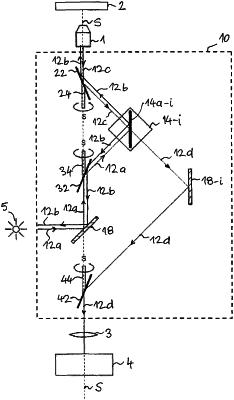
1. An assembly (10, 10′, 10″) for switching optical paths in an optical microscope, said assembly comprising multiple optical channels for guiding an illuminating light to a specimen and for guiding the light coming from the specimen to an image recording unit, the assembly further comprising a plurality of light guiding mirrors and at least one light modifying element in each optical channel for directing the illuminating light and the light coming from the specimen,
characterized in that
the light modifying elements comprise a stationary dichroic mirror (14a-i); and
the light guiding mirrors include the following mirrors:
a first rotatable light guiding mirror (32) for directing the illuminating light ray (12a) to a selected dichroic mirror (14a-i),
a second rotatable light guiding mirror (22) for guiding a light ray (12b) reflected by the dichroic mirror (14a-i) to the specimen and for directing a light ray (12c) coming from the specimen to the dichroic mirror (14a-i), and
multiple third stationary light guiding mirrors (18-i), each forming a pair with a respective dichroic mirror (14a-i) and adapted for reflecting a light ray (12d) passing through the respective dichroic mirror (14a-i), and
a fourth rotatable light guiding mirror (42) for directing the light ray (12d) reflected by one of the third light guiding mirrors (18-i) towards the image recording unit (4);
wherein a rotating unit is coupled to the first, second and fourth light guiding mirrors (32, 22, 42), and a rotational axis of said light guiding mirrors (32, 22, 42) aligns with a common geometric axis (S); and
wherein the dichroic mirrors (14a-i) associated with the respective optical channels and the third light guiding mirrors (18-i) are arranged around said geometric axis (S).
|