| CPC G01V 3/12 (2013.01) [E21D 11/00 (2013.01)] | 14 Claims |

|
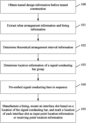
1. A method for non-destructive testing of a tunnel lining, comprising:
obtaining tunnel design information before tunnel construction;
extracting rebar arrangement information and lining information based on the tunnel design information;
performing matching analysis on the tunnel design information based on arrangement interval information stored in a preset arrangement database, to determine an arrangement interval corresponding to the tunnel design information, and defining the arrangement interval as theoretical arrangement interval information, wherein the theoretical arrangement interval information is about an interval distance that is in a length direction of an arc of a lining between a signal conducting bar added to the lining and rebars on two sides each, and information about an interval distance between a signal conducting bar and a signal conducting bar;
determining location information of a signal conducting bar group based on the lining information and the theoretical arrangement interval information, wherein each of signal conducting bar groups comprises a signal-transmission conducting bar and a signal-reception conducting bar, one end of the signal-transmission conducting bar is a signal transmitting point, the other end of the signal-transmission conducting bar is a signal input connection point, one end of the signal-reception conducting bar is a signal receiving point, and the other end of the signal-reception conducting bar is a signal output connection point;
pre-embedding signal conducting bars in sequence based on the location information of the signal conducting bar group, wherein the signal transmitting point and the signal receiving point are located on a side, close to a geotechnical layer, of the lining, and the signal input connection point and the signal receiving point are located on a side, away from the geotechnical layer, of the lining; and
manufacturing the lining, mounting an interface slot based on a location of the signal conducting bar, and marking a location of each interface slot as input point location information or receiving point location information, wherein the input point location information indicates a location corresponding to the signal input connection point, and the receiving point location information indicates a location corresponding to the signal receiving point;
wherein the method for non-destructive testing of a tunnel lining further comprises a process for testing by a main machine, comprising:
obtaining first test region information;
performing matching analysis on the first test region information based on the input point location information and the receiving point location information that are stored in a preset distribution database, to determine an input point location and a receiving point location that are corresponding to the first test region information, defining the input point location as current input point location information, and defining the receiving point location as current receiving point location information;
after enabling the main machine to travel to the first test region information along a preset track, inserting a transmitting terminal of the main machine at the current input point location information, to be connected to a corresponding signal input connection point, and inserting a receiving terminal of the main machine at the current receiving point location information, to be connected to a corresponding signal output connection point;
converting, by the transmitting terminal of the main machine, a preset first digital transmission signal into a preset first analog signal by an encoder mounted on the transmitting terminal of the main machine, and inputting the preset first analog signal from a signal input connection point corresponding to the current input point location information, transmitting, by a signal-transmission conducting bar corresponding to the current input point location information, an analog signal, receiving a preset first waveform signal at a signal-reception conducting bar corresponding to the current receiving point location information, sending the preset first waveform signal to the receiving terminal of the main machine from a signal-reception connection point corresponding to the current receiving point location information, and converting, by the receiving terminal of the main machine, the preset first waveform signal into a first digital reception signal by a decoder mounted on the receiving terminal of the main machine;
analyzing the first digital reception signal, to obtain first test result information;
after obtaining the first test result information, enabling the main machine to travel to a next region until all regions have been tested.
|