| CPC G01R 21/1331 (2013.01) [G01R 19/2513 (2013.01); G01R 31/088 (2013.01)] | 1 Claim |
|
1. A method for estimating area-level inertia in a power system, comprising:
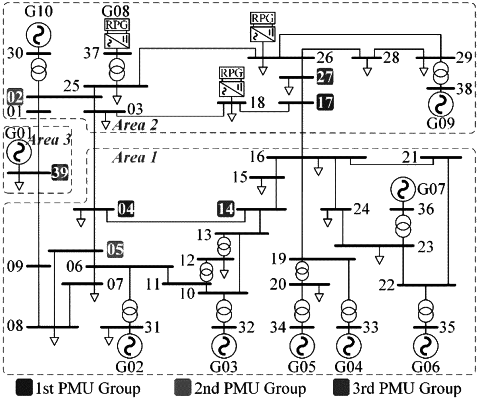
partitioning the power system as a multi-area system, wherein:
a phasor measurement unit (“PMU”) is placed at a bus in at least one area of the multi-area system; and
for an N-th area which contains only one generator and one bus, the PMU placement must be placed at the multi-area system;
measuring bus frequencies, power flow related data including amplitude and phase angle of bus voltage by the PMUs or SCADA/EMS as follows:
| ||||||||||||||||||||||||||
specifying data window for inertia estimation during small disturbance situations;
preparing measured frequencies within the data window, wherein:
for the power flow data, variables at a linearization point correspond to a head of the data window, and variables at a system steady-state are utilized; and
determining an internal reactance or an inertia of the N-th area according to an identifiability analysis;
estimating the area-level inertia by:
 fB,i=g(Ψ,fCOI,i(0),δCOI,i(0),ECOI,i(ss),δCOI,i(ss),Ui(ss),θi(ss)), (11c)
wherein t0 is a moment corresponding to a linearization point; T is a data window length; a vector Ψ consisting of parameters to be estimated in (11b); based on Ψ and power flow related variables, bus frequency dynamics are estimated in (11c);
wherein g(⋅) denotes:
  where KA,i is a linearization coefficient of a generator active power; the superscript {⋅}(ss) denotes a steady-state value; and where KA,i is a linearization coefficient of an inter-area active power;
obtaining an area equivalent internal reactance and an equivalent inter-area line reactance;
determining a real-time frequency stability level and a real-time degree of frequency spatial distribution based on the area equivalent internal reactance and the equivalent inter-area line reactance;
issuing an alarm in the event of a determined frequency instability; and
when an online inertia level is low, allocating optimal inertia from battery storage and unit commitment optimization of synchronous generators;
wherein:
 transient processes of variables in (7)-(9) are determined by the initial conditions of state variables fCOI,i, δCOI,i, and θi;
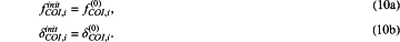
in (7a) and (7b), the initial conditions of the state variables fCOI,i δCOI,i are their values at linearization points:
 θi in (8) is a dependent variable of the state variables.
|
||||||||||||||||||||||||||