| CPC G01N 30/8675 (2013.01) [G01N 30/32 (2013.01); G01N 2030/027 (2013.01)] | 7 Claims |

|
1. A liquid chromatograph comprising:
a liquid sending system having an analysis flow path and including:
a liquid sending pump for sending a mobile phase through the analysis flow path;
a sample injector that injects a sample into the mobile phase flowing through the analysis flow path;
a separation column provided on the analysis flow path and configured to separate the injected sample into components; and
a pressure sensor for detecting a liquid sending pressure in the analysis flow path, wherein the pressure sensor is located at a position farther upstream along the analysis flow path than the separation column;
computer circuitry configured to:
hold in memory a capacity value representing an internal capacity of the liquid sending system;
determine a reference fluctuation range of the liquid sending pressure based on the capacity value; and
periodically acquire liquid sending pressures detected by the pressure sensor;
obtain a fluctuation range of the liquid sending pressure in a certain during a driving period of the liquid sending pump; and
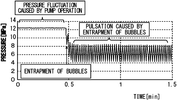
detect a liquid sending failure based on the obtained fluctuation range and the reference fluctuation range.
|