| CPC F16L 55/44 (2013.01) [B25J 5/007 (2013.01); B25J 19/023 (2013.01); F16L 2101/30 (2013.01)] | 20 Claims |
|
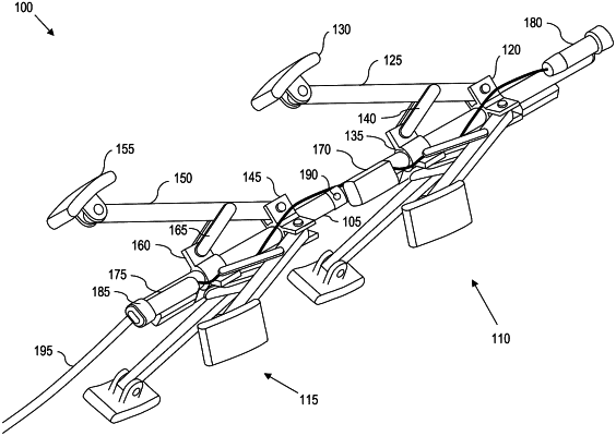
1. A robotic in-pipe inspection system, comprising:
a center shaft comprising:
a shaft front portion;
a shaft rear portion; and
a shaft connector mechanically coupling the shaft front portion to the shaft rear portion at a shaft angle, the shaft angle ranging from ninety degrees (90°) to one-hundred-and-eighty degrees (180°);
a front leg assembly operatively coupled to the shaft front portion, the front leg assembly comprising:
a front leg connector mechanically coupled to the shaft front portion;
a first front leg comprising a proximal end and a distal end, the proximal end of the first front leg being mechanically and pivotally coupled to the front leg connector at a first front angle, the first front leg being at a first front azimuthal position;
a first front contact means for contacting an inner surface of a pipe, the first front contact means being mechanically coupled to the distal end of the first front leg;
a front slider slidably coupled to the shaft front portion; and
a first front lever arm pivotally coupled to the first front leg, the first front lever arm further being pivotally coupled to the front slider;
a second front leg comprising a proximal end and a distal end, the proximal end of the second front leg being mechanically and pivotally coupled to the front leg connector at a second front angle, the second front leg being at a second front azimuthal position;
a second front contact means for contacting the inner surface of the pipe, the second front contact means being mechanically coupled to the distal end of the second front leg;
a second front lever arm pivotally coupled to the first front leg, the first front lever arm further being pivotally coupled to the front slider;
a rear leg assembly operatively coupled to the shaft rear portion, the rear leg assembly comprising:
a rear leg connector mechanically coupled to the shaft rear portion;
a first rear leg comprising a proximal end and a distal end, the proximal end of the first rear leg being mechanically and pivotally coupled to the rear leg connector at a first rear angle, the first rear leg being at a first rear azimuthal position;
a first rear contact means for contacting the inner surface of the pipe, the first rear contact means being mechanically coupled to the distal end of the first rear leg;
a rear slider slidably coupled to the shaft rear portion; and
a first rear lever arm pivotally coupled to the first rear leg, the first rear lever arm further being pivotally coupled to the rear slider;
a second rear leg comprising a proximal end and a distal end, the proximal end of the second rear leg being mechanically and pivotally coupled to the rear leg connector at a second rear angle, the second rear leg being at a second rear azimuthal position;
a second rear contact means for contacting the inner surface of the pipe, the second rear contact means being mechanically coupled to the distal end of the second rear leg;
a second rear lever arm pivotally coupled to the first rear leg, the first rear lever arm further being pivotally coupled to the rear slider;
a shaft controller operatively coupled to the shaft front portion and the shaft rear portion, the shaft controller for controlling the shaft angle;
a front controller operatively coupled to the front leg assembly, the front controller for controlling the first front angle, the front controller further for controlling the second front angle; and
a rear controller operatively coupled to the rear leg assembly, the rear controller for controlling the first rear angle, the rear controller further for controlling the second rear angle;
a targeted field-of-view inspection camera for visually inspecting an area of interest within the pipe; and
a robot-body-facing camera for visually examining the robotic in-pipe inspection system.
|