| CPC F04B 47/12 (2013.01) [E21B 43/122 (2013.01)] | 3 Claims |

|
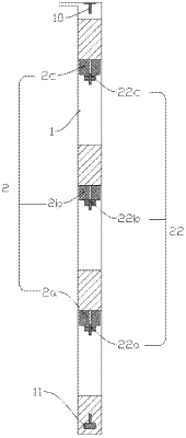
1. A liquid drainage method of a multi-plunger cooperated gas lift liquid drainage system, the multi-plunger cooperated gas lift liquid drainage system comprising: a tubing string and a plurality of plungers arranged in the tubing string successively from top to bottom; wherein a wellhead poke rod is arranged at a top of the tubing string, a tubing stop is arranged at a bottom of the tubing string;
each of the plurality plungers comprising a valve body, a cavity fluidly communicated with a lower end of the valve body, a valve spool disposed in the cavity, and a valve stem passing through a bottom wall of the cavity and fixedly connected to a lower end of the valve spool;
a through hole penetrating through an upper wall of the valve body and formed in the valve body wherein a lower end of the through hole is fluidly communicated with a valve seat hole, the valve seat hole penetrates through the lower end of the valve body;
the liquid drainage method comprising following steps:
Step 1: installing the tubing stop on a lower portion of the tubing string in a well; opening the well for allowing liquid and gas to flow in and accumulate at a bottom of the tubing string;
dropping a first plunger with a first valve spool in an open position into the tubing string, wherein the first plunger falls through an accumulated liquid while the accumulated liquid is flowing to an upper position above the first plunger, and collides with the tubing stop to close the first valve, the first plunger gets itself sealed when the first valve spool is closed, and then the first plunger and an upper accumulated liquid thereon is pushed upward by the gas accumulated at the bottom of the tubing string;
Step 2: when the first plunger rising to a first certain height, dropping a second plunger with a second valve spool in an open position into the tubing string, wherein the second plunger falls through an upper accumulated liquid on the first plunger to collide with the first plunger, causing the first valve spool to be opened, the second valve spool to be closed, the upper accumulated liquid on the first plunger to transfer to an upper position above the second plunger, and the second plunger and an accumulated liquid thereon to be pushed upward by a second gas column, the first plunger loses the sealing function due to the first valve spool opened and falls to the tubing stop to reclose the first valve spool under an influence of gravity, a newly formed liquid column at the tubing stop is pushed again to ascend under the action of the gas accumulated at the bottom of the tubing string, and at this moment, two small-section liquid columns are formed in the tubing string and pushed upward by two gas column sections the sealing effect of the two plungers;
Step 3: when the second plunger rising to a second certain height, dropping a third plunger with a third valve spool in an open position, wherein the third plunger meets the second plunger to transfer a liquid load, close the third valve spool, and open the second valve spool, the third plunger reverses and pushes a liquid column thereon upward, the second plunger reverses and moves downward, and then the second plunger meets the first plunger to transfer a liquid load, close the second valve spool, and opens the first valve spool, the second plunger reverses and pushes a liquid column thereon upward, the first plunger reverses to move downward, collides with the tubing stop to close the first valve spool, and again pushes a liquid column thereon upward, at this moment, three small-section liquid columns are formed in the tubing string and pushed upward by three gas column sections under the sealing effect of the three plungers;
Step 4: each time when the first plunger rising of the plurality of plungers to a certain height, dropping the second plunger of the plurality of plungers which is next to the first plunger into the tubing string, and so on, until the last plunger of the plurality of plungers rising to a last certain height, liquid loads are sequentially transferred between the plungers, so that multiple liquid column sections and multiple gas column sections are formed in the tubing string and move upward simultaneously; wherein the plurality of plungers is determined according to actual needs of the well;
Step 5: installing a wellhead poke rod at a wellhead of the tubing string; wherein an uppermost plunger moves upward to the wellhead with an accumulated liquid and gas on the uppermost plunger being discharged from the tubing string, collides with the wellhead poke rod to open its valve spool, and falls downward;
Step 6: allowing the uppermost plunger to falls down, wherein the uppermost plunger collides with a plunger thereunder and transfer a liquid load, the uppermost plunger again moves upward to push an accumulated liquid thereon and gas above itself out of the tubing string, the plunger below the uppermost plunger falls downward, the plungers collide with each other to sequentially transfer liquid loads, by analogy, the system runs reciprocating cycle to discharge an accumulated liquid and gas produced at the bottom of the tubing string, every time a small section of liquid column and gas column are discharged, the pressure of all gas columns in the tubing string is reduced, and the gas columns expand stage by stage, act as a driving force together with the gas produced at the bottom of the well, to push the liquid columns at all stages upward.
|