| CPC F02C 7/224 (2013.01) [F02C 7/14 (2013.01); F02C 7/32 (2013.01); F05D 2260/20 (2013.01)] | 14 Claims |

|
1. A method of operating an aircraft propulsion system, the aircraft propulsion system comprising:
a gas turbine engine, the gas turbine engine comprising:
an engine core comprising a turbine, a compressor, a combustor arranged to combust a fuel, and a core shaft connecting the turbine to the compressor;
a fan located upstream of the engine core;
a fan shaft;
a gearbox that receives an input from the core shaft and outputs drive to the fan via the fan shaft;
a heat exchange system comprising at least one fuel-oil heat exchanger arranged to transfer heat to the fuel;
a fuel pump arranged to deliver the fuel to the combustor, wherein the fuel pump is located downstream of the at least one fuel-oil heat exchanger;
a controller configured to control the heat exchange system; and
the fuel,
wherein the heat exchange system includes:
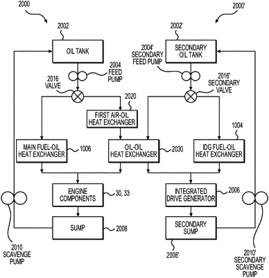
a primary oil loop system arranged to supply oil to the gearbox, wherein the at least one fuel-oil heat exchanger comprises at least a primary fuel-oil heat exchanger and a secondary fuel-oil heat exchanger, the primary fuel-oil heat exchanger being arranged such that the oil of the primary oil loop system and fuel flows therethrough to transfer heat from the oil to the fuel;
an integrated drive generator; and
a secondary oil loop system arranged to provide oil to the integrated drive generator;
wherein the secondary fuel-oil heat exchanger is arranged such that oil from the secondary oil loop system and the fuel flows therethrough to transfer heat between the oil from the secondary oil loop system and the fuel, and
the primary oil loop system, the secondary oil loop system, the primary fuel-oil heat exchanger and the secondary fuel-oil heat exchanger are arranged such that the fuel flows through the secondary fuel-oil heat exchanger prior to flowing through the primary fuel-oil heat exchanger to transfer heat from the oil in the secondary oil loop system to the fuel before heat is transferred from the oil in the primary oil loop system to the fuel,
wherein the controller is configured to control the heat exchange system so as to adjust a lubricity of the fuel so that the fuel has a lubricity of between 0.71 mm and 0.90 mm wear scar diameter (WSD) at 25° C., the controller configured to control fuel flow through one or both of the primary fuel-oil heat exchanger and the secondary fuel-oil heat exchanger,
wherein the method comprises
controlling the heat exchange system so as to adjust the lubricity of the fuel so that the lubricity of the fuel is between 0.71 mm and 0.90 mm wear scar diameter (WSD) at 25° C., the controlling including controlling fuel flow through one or both of the primary fuel-oil heat exchanger and the secondary fuel-oil heat exchanger, the fuel including sustainable aviation fuel (SAF) in an amount up to and including 100% SAF.
|
|
8. An aircraft propulsion system, comprising:
a gas turbine engine comprising:
an engine core comprising a turbine, a compressor, a combustor arranged to combust a fuel, and a core shaft connecting the turbine to the compressor;
a fan located upstream of the engine core;
a fan shaft;
a gearbox arranged to receive an input from the core shaft and output drive to the fan via the fan shaft;
a heat exchange system comprising at least one fuel-oil heat exchanger arranged to transfer heat to the fuel;
a fuel pump arranged to deliver the fuel to the combustor, wherein the fuel pump is located downstream of the at least one fuel-oil heat exchanger;
a controller configured to control the heat exchange system; and
the fuel,
wherein the heat exchange system includes:
a primary oil loop system arranged to supply oil to the gearbox, wherein the at least one fuel-oil heat exchanger comprises at least a primary fuel-oil heat exchanger and a secondary fuel-oil heat exchanger, the primary fuel-oil heat exchanger being arranged such that the oil of the primary oil loop system and fuel flows therethrough to transfer heat from the oil to the fuel;
an integrated drive generator; and
a secondary oil loop system arranged to provide oil to the integrated drive generator;
wherein the secondary fuel-oil heat exchanger is arranged such that oil from the secondary oil loop system and the fuel flows therethrough to transfer heat between the oil from the secondary oil loop system and the fuel, and
the primary oil loop system, the secondary oil loop system, the primary fuel-oil heat exchanger and the secondary fuel-oil heat exchanger are arranged such that the fuel flows through the secondary fuel-oil heat exchanger prior to flowing through the primary fuel-oil heat exchanger to transfer heat from the oil in the secondary oil loop system to the fuel before heat is transferred from the oil in the primary oil loop system to the fuel,
wherein the controller is configured to control the heat exchange system so as to adjust a lubricity of the fuel so that the fuel has a lubricity of between 0.71 mm and 0.90 mm wear scar diameter (WSD) at 25° C., the controller configured to control fuel flow through one or both of the primary fuel-oil heat exchanger and the secondary fuel-oil heat exchanger, and the fuel includes sustainable aviation fuel (SAF) in an amount up to and including 100% SAF.
|