| CPC F02C 3/22 (2013.01) [C01B 3/047 (2013.01); B01D 2256/16 (2013.01); C01B 2203/0266 (2013.01); C01B 2203/0277 (2013.01); C01B 2203/041 (2013.01); F02C 3/20 (2013.01); F02C 7/22 (2013.01); F02C 7/224 (2013.01); F02C 9/40 (2013.01); F23R 3/40 (2013.01)] | 9 Claims |

|
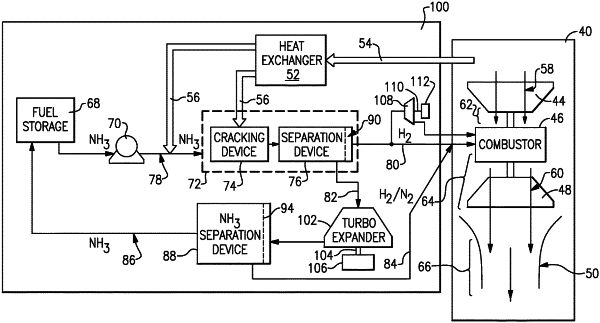
1. A gas turbine engine comprising:
a cracking device configured to decompose an ammonia flow into a flow containing more hydrogen (H2) than ammonia (NH3);
a first separation device where the flow containing more hydrogen than ammonia is received from the cracking device, the first separation device is configured for separating hydrogen from residual ammonia and nitrogen, wherein residual ammonia and nitrogen are exhausted as a residual flow, and a flow that contains more hydrogen than ammonia and nitrogen is exhausted separately as a hydrogen flow;
a combustor configured to receive and combust the hydrogen flow from the first separation device to generate a gas flow;
a second separation device downstream of the first separation device, the second separation device configured to receive the residual flow, separate ammonia from hydrogen and nitrogen, communicate the separated ammonia to a fuel storage tank and communicate the hydrogen and nitrogen to the combustor;
a compressor section configured to supply compressed air to the combustor; and
a turbine section in flow communication with the gas flow produced by the combustor and mechanically coupled to drive the compressor section.
|