| CPC F01D 5/189 (2013.01) [F01D 5/20 (2013.01); F05D 2260/201 (2013.01); F05D 2260/204 (2013.01)] | 22 Claims |

|
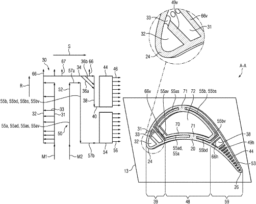
1. A turbine blade for a gas turbine which is flowed through axially for a high-pressure turbine stage thereof, comprising:
a blade root and a blade airfoil comprising a pressure-side side wall and a suction-side side wall, wherein the pressure-side side wall and the suction-side side wall extend along a spanwise direction from a root-side end to a blade tip and along a chordwise direction, which is oriented transversely to the spanwise direction, from a leading edge to a trailing edge,
wherein, in an interior of the blade airfoil, a first cooling path for a first coolant stream and a second cooling path, substantially separated from the first cooling path, for a second coolant stream are formed,
wherein the first cooling path comprises
a first coolant passage, which is configured for cyclone cooling of the leading edge, and
a second coolant passage, which adjoins the first coolant passage and extends below the blade tip from the leading edge in the direction of the trailing edge,
wherein the second cooling path comprises
a serpentine coolant passage for cooling of a middle region of the blade airfoil, which middle region is arranged behind a leading-edge region in the chordwise direction, and
a first trailing-edge coolant passage for at least partial cooling of a trailing-edge region of the blade airfoil, which trailing-edge region is arranged behind the middle region in the chordwise direction and extends as far as the trailing edge,
wherein the first trailing-edge coolant passage is connected in terms of flow to a multiplicity of first exit holes arranged in the trailing edge,
wherein the first coolant passage and/or the serpentine coolant passage are/is free of exit holes, and
wherein the first cooling path comprises
a third coolant passage, which adjoins the second coolant passage and extends mainly radially inwardly, and
a second trailing-edge coolant passage, which adjoins the third coolant passage and is configured for cooling of a blade-tip-side region of the trailing-edge region and is connected in terms of flow to a multiplicity of second exit holes arranged in the trailing edge;
wherein the serpentine coolant passage comprises at least two channel sections, extending in the spanwise direction, and at least two reversal sections, wherein the reversal section situated further downstream in the second coolant stream is connected in terms of flow directly to the first trailing-edge coolant passage;
wherein the at least two channel sections, by a displacement body and by the pressure-side side wall and the suction-side side wall, are, in a cross-sectional view of the blade airfoil, each of substantially C-shaped form with a suction-side channel arm, a pressure-side channel arm and a connecting arm connecting the suction-side channel arm and the pressure-side channel arm and are arranged in relation to one another to surround the displacement body.
|