| CPC F01D 5/18 (2013.01) [F05D 2220/32 (2013.01); F05D 2230/60 (2013.01); F05D 2260/20 (2013.01)] | 16 Claims |

|
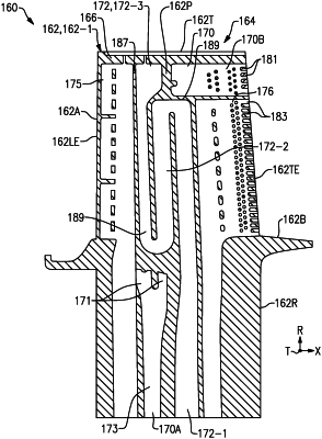
1. An airfoil for a gas turbine engine comprising:
an airfoil section extending in a radial direction from a root section to a tip portion, the airfoil section having an external wall and an internal wall, the external wall defining pressure and suction sides extending in a chordwise direction between a leading edge and a trailing edge, and the pressure and suction sides spaced apart in a thickness direction between the leading edge and the trailing edge; and
wherein the airfoil section establishes an internal cooling arrangement comprising:
a first cooling passage including a first section and a tip flag section, the first section extending in the radial direction from the root section, and the tip flag section extending in the chordwise direction along the tip portion from the first section to the trailing edge;
wherein the first section includes a plurality of branched paths established by at least one turning vane that interconnects the internal wall and the external wall, the at least one turning vane having an arcuate profile and arranged such that the plurality of branched paths join together along the tip flag section;
wherein the internal wall extends in the chordwise direction such that the plurality of branched paths are bounded in the thickness direction between the internal wall and the external wall adjacent the at least one turning vane;
a serpentine cooling passage including a first section, a second section and a third section, the second section interconnecting the first section and the third section, and the first section extending outwardly from the root section and the third section extending inwardly from the tip portion relative to the radial direction; and
wherein the tip flag section and the third section of the serpentine cooling passage are situated on opposite sides of the internal wall relative to the thickness direction.
|