| CPC E05B 41/00 (2013.01) [E05B 15/02 (2013.01); E05Y 2900/132 (2013.01); Y10S 292/61 (2013.01); Y10T 292/0977 (2015.04)] | 18 Claims |

|
1. A status indicator assembly for a locking mechanism, the locking mechanism moveable between a locked state and an unlocked state, the locking mechanism coupled to an actuation mechanism, the actuation mechanism operatively coupled to the status indicator such that movement of the locking mechanism moves the status indicator, the status indicator assembly comprising:
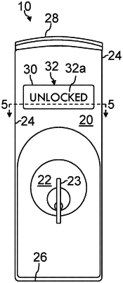
an escutcheon plate having a curved front face portion, wherein the curvature of the front face portion includes at least two radii of curvature;
an indicator window disposed on the front face portion of the escutcheon plate;
a status indicator having a status indicator plate and a status indicator face, the status indicator operatively couplable to the locking mechanism, the status indicator disposed behind the escutcheon plate and visible through the indicator window,
wherein the status indicator displays a locked indication when the locking mechanism is in the locked state, and wherein the status indicator displays an unlocked indication when the locking mechanism is in the unlocked state, and wherein the curvature of the of the front face portion allows the front face portion to be visible through the indicator window from a viewing angle greater than or equal to 180 degrees; and
a biasing element configured to couple the status indicator face to the status indicator plate, wherein the biasing element allows the status indicator face to be moved independently relative to the status indicator plate.
|