| CPC B66D 1/06 (2013.01) [B66D 3/14 (2013.01); B66D 5/14 (2013.01); B66D 5/34 (2013.01); B66D 2700/05 (2013.01)] | 20 Claims |

|
1. A lifting gear, comprising:
a housing;
a load chain wheel;
a drive shaft configured to drive the load chain wheel via a transmission, wherein the load chain wheel and the drive shaft are rotatably supported in the housing;
a load pressure brake;
a safety brake; and
a load chain movable via the load chain wheel,
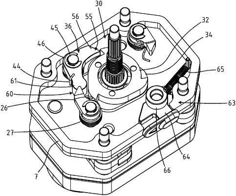
wherein the safety brake exhibits
a locking disc with locking teeth,
a control disc with control cams, and
a catch hook,
wherein the locking disc and the control disc are held by the drive shaft and rotatable in a relative rotation with respect to each other,
wherein the relative rotation is limited by a rotation limiter,
wherein the catch hook is arranged so that the catch hook is movable in a swiveling manner,
wherein the catch hook exhibits a latch contour on a front end and a sensing contour on a rear end,
wherein the sensing contour rests under the effect of a spring element on the control disc,
wherein, with increasing acceleration of the drive shaft, the sensing contour lifts from the control disc with excessive rotational speed and the latch contour is brought to engage lockingly with a locking tooth of the locking disc to hold the locking disc while the control disc continues to turn along a specified rotational path of the rotation limiter until the rotational path is exhausted and the locking disc and the control disc interlock, wherein the control disc actively pushes the catch hook into the locking tooth of the locking disc to obtain a locked position in which the control disc also prevents the catch hook from turning back, so that the safety brake is locked, and
wherein the catch hook is trapped at both ends thereof such that the catch hook is caught at said both ends by the control cam and the locking tooth such that the control disc fits into a pocket of the catch hook.
|