| CPC B65G 17/062 (2013.01) [B65G 25/06 (2013.01); B65G 67/24 (2013.01); B65G 17/08 (2013.01); B65G 17/40 (2013.01)] | 15 Claims |

|
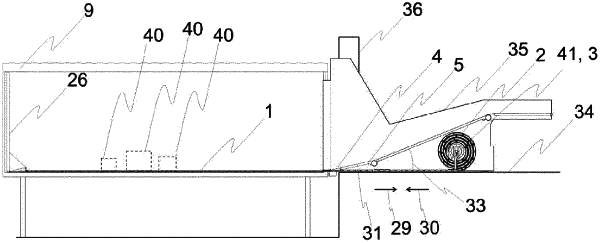
1. A load carrier for loading and unloading a container, comprising rigid load-carrier segments,
wherein the load-carrier segments each have an upper side facing in a third direction and a segment length extending in a first direction and a segment width extending in a second direction, wherein the first direction, the second direction and the third direction are disposed mutually normal to one another,
wherein, in a first state of the load carrier, the upper sides of the load-carrier segments are arranged substantially parallel to one another and, as seen in the first direction, one behind the other in order to form a substantially planar loading area,
wherein the load-carrier segments are connected to one another in an articulated manner such that the load-carrier segments can be pivoted in relation to one another about pivot axes extending parallel to the second direction, wherein, in the first state, a respective one of the load-carrier segments, which, as viewed in the first direction, follows a respectively other one of the load-carrier segments, can be pivoted with its upper side in the direction of the upper side of the other load-carrier segment in order to be able to transfer the load carrier from the first state into a second state by at least sectionally rolling up the load-carrier segments in spiral form,
wherein the load carrier can be transferred from the second state into the first state by unrolling,
wherein the load-carrier segments each have at least one cover plate,
wherein the cover plates have grooved structures which form the upper sides of the load-carrier segments,
wherein the load-carrier segments each have at least two carrier slats to which the at least one cover plate is fastened, in particular screwed tightly, wherein the carrier slats of the respective load-carrier segment extend in the second direction and are arranged parallel to one another, wherein in each case two of the carrier slats of the respective load-carrier segment are arranged one behind the other, as seen in the first direction,
and wherein the carrier slats of successive load-carrier segments are shaped in such a way that, in the first state of the load carrier, they overlap in sections in the first direction.
|