| CPC B60H 1/3407 (2013.01) [B60H 1/3457 (2013.01); F24F 13/072 (2013.01)] | 6 Claims |

|
1. An air discharge device comprising:
an air discharge unit configured to discharge air, wherein
the air discharge unit includes
at least one main hole from which an air flow is blown out as a working air flow, and
a fixed separation structure configured to separate a central portion of a thickness of a velocity boundary layer of the working air flow from a center line of the main hole at a downstream side of the main hole, wherein
the air discharge unit includes a main flow passage through which the working air flow to be blown from the main hole passes,
the separation structure includes a layer reduction structure configured to reduce the thickness of the velocity boundary layer formed along an inner wall surface of the main hole,
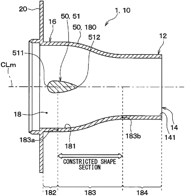
the layer reduction structure includes a contraction structure having a teardrop shaped cross-section provided in the main flow passage, the contraction structure being configured to contract the air flow flowing through the main flow passage,
an inner wall surface defining the main flow passage has a contracted shape section configured to reduce a passage cross-sectional area of the main flow passage from an upstream side to a downstream side in an air flow direction, and
a downstream end of the contraction structure, located at a downstream side in the air flow direction of the main flow passage, is positioned downstream of an upstream end of the contracted shape section in the air flow direction of the main flow passage.
|