| CPC B60B 35/1045 (2013.01) [B60B 35/1081 (2013.01)] | 5 Claims |

|
1. A track width adjustment (TWA) mechanism, comprising:
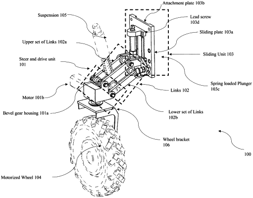
a steer and drive unit, wherein the steer and drive unit comprises:
a bevel gear housing, wherein the bevel gear housing is configured to accommodate a first bevel gear and a second bevel gear which provide connection between two shafts which lie at a pre-defined angle to each other for transmission of motion and force, wherein the first bevel gear and the second bevel gear are connected at a predefined angle to each other, and a shaft end of the first bevel gear is connected to a motor and a shaft end of the second bevel gear is connected to a wheel bracket, forming a gear train;
the motor, wherein the motor is mounted on a support provided on a first outer face of the bevel gear housing, wherein the motor is connected to the first bevel gear and causes rotation of the first bevel gear, and wherein the gear train transmits motion and force from the motor through the first bevel gear and the second bevel gear to the wheel bracket, causing the wheel bracket to rotate which further causes a motorized wheel connected to the wheel bracket to rotate about the axis of the second bevel gear; and
a thrust bearing and a radial bearing, wherein the thrust bearing and the radial bearing are held at an intended position by a flange housing with one or more spacers;
a plurality of links comprising an upper set of links and a lower set of links, wherein,
a first end of each of the plurality of links is connected to the bevel gear housing and a second end of each of the plurality of links is connected to a sliding plate, wherein the plurality of links form a connection between the steer and drive unit and a sliding unit, wherein the plurality of links carry transfer of load between a chassis and the motorized wheel,
wherein the lower set of links encompasses a slot for a suspension system that transmits the load to the suspension system, and
wherein the upper set of links and the lower set of links pivot and rotate around a connection at the first end of the plurality of links, and
the second end of each of the plurality of links which is connected to the bevel gear housing and the sliding plate respectively, wherein the rotation of the upper set of links and the lower set of links provides a coherent motion when the sliding plate moves in the first direction and the second direction vertically while the motorized wheel rolls inwards and outwards of the chassis respectively,
wherein the sliding unit comprises:
the sliding plate, wherein a first end of the sliding plate is connected to the plurality of links and a second end of the sliding plate is mounted on a Linear Motion (LM) carriage, wherein the LM carriage slides over a plurality of LM rails mounted onto an attachment plate,
wherein the attachment plate is configured for fixing and connecting the TWA mechanism with the chassis, wherein a back surface of the attachment plate is attached to the chassis, wherein the attachment plate comprises a plurality of locating holes for connecting a spring-loaded plunger, and wherein the spring-loaded plunger has a locking element with a pin with an attached pull knob for adjusting position of the locking element, wherein when the attached pull knob of the spring-loaded plunger is in a first position, an opposite end of the spring-loaded plunger moves inside one of a plurality of holes in the attachment plate to constraint the motion of the sliding plate,
wherein when the pull knob of the spring-loaded plunger is in a second position the opposite end of the spring-loaded plunger moves back and detaches from the hole, causing the sliding unit to slide with motion of the plurality of links; and
a lead screw, wherein the lead screw is fixed at top end of the sliding unit with a fixed nut, wherein the lead screw is configured to rotate on an associated axis, wherein rotation of the lead screw causes (i) the sliding plate to move in a first direction and a second direction, (ii) movement of the plurality of links, and (iii) shift in the position of the motorized wheel.
|