| CPC B41F 27/105 (2013.01) [B41F 27/02 (2013.01); B41F 27/14 (2013.01); B41P 2227/20 (2013.01)] | 19 Claims |

|
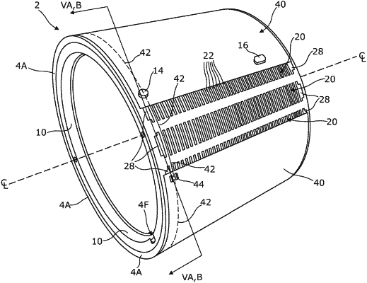
1. A sleeve assembly (2) comprising a cylindrical tube (4), formed from one of: an engineering plastics material, a metal or an alloy thereof, having a density less than 3.5 g/cm3 and having exterior and interior cylindrical surfaces extending generally between a pair of annular end surfaces (4A), said tube having machined or otherwise provided therein a plurality of recesses (12) substantially completely occupied by comparatively rigid magnetic means (20) which are firmly secured therein, said recesses being of substantially uniform depth along their length, and being uniformly spaced apart circumferentially of the tube and extending axially from one end of the tube to another end of the tube over substantially the entire axial length of the tube, wherein said sleeve assembly further comprises a tubular radially compressible liner (6) which is shorter in axial length than the cylindrical tube and which is bonded inside said tube to the interior cylindrical surface thereof axially centrally thereof thus leaving interior cylindrical end regions (4B) of the tube exposed beyond the annular end surfaces (6A) of said liner, said interior cylindrical end regions having rebates (8) extending radially outwardly from the circular interface between said liner and said tube so as to define annular shoulders (4D) within the interior of the tube at either end thereof, said interior cylindrical end regions being provided with screw threads (4C) so as to be capable of receiving a pair of correspondingly threaded end rings (10) constituted of a material having a modulus of elasticity which is at least twice that of the material of which the cylindrical tube is constituted, and having an inner diameter which is greater than the inner diameter of the compressible liner thus allowing the interior cylindrical surface of said liner to be radially expanded towards a position in which the interior cylindrical surface lies substantially flush with an inner cylindrical surface of said end rings, and
wherein said annular shoulders (4D) are provided internally of the tube at a relatively shallower axial depth from the respective annular end surfaces (4A) of said tube than the axial distance between the terminal end of at least one of the recesses (12) and the annular end surfaces of the tube most proximate thereto, the arrangement being that when said end rings are screwed fully into said rebates and into abutting relationship with the annular shoulders and tightened thereagainst, not only do said end rings exert axial compression on the cylindrical tube, but said end rings also provide underlying structural support for the end regions of the sleeve assembly underneath said at least one recess.
|