| CPC B29C 64/165 (2017.08) [B22F 10/14 (2021.01); B22F 10/28 (2021.01); B22F 12/13 (2021.01); B22F 12/45 (2021.01); B22F 12/67 (2021.01); B29C 64/209 (2017.08); B29C 64/218 (2017.08); B29C 64/236 (2017.08); B29C 64/277 (2017.08); B29C 64/282 (2017.08); B29C 64/314 (2017.08); B33Y 10/00 (2014.12); B33Y 30/00 (2014.12); B33Y 40/10 (2020.01); B22F 10/68 (2021.01); B22F 10/73 (2021.01); B22F 12/41 (2021.01); B22F 12/90 (2021.01)] | 11 Claims |

|
1. A method of manufacturing a three-dimensional object from a powder using an apparatus to form each layer of the object, wherein the apparatus comprises:
a build bed having a build area, wherein successive layers of said three-dimensional object are formed in the build bed;
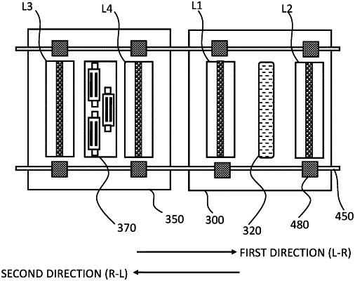
a powder distribution sled operable to distribute a layer of powder within the build area, the powder distribution sled being driveable in a first direction along a first axis, across the build area, and driveable in a second direction, opposite to the first direction, along the first axis; and
a print sled operable to deposit a pattern of radiation absorbing fluid onto the layer of powder within the build area to define the cross section of said object in said layer, the print sled being driveable in the first direction along a second axis across the build area, and driveable in the second direction along the second axis;
wherein the first axis is parallel to, or coaxial with, the second axis;
wherein the powder distribution sled and the print sled are independently movable;
wherein the print sled comprises one or more droplet deposition heads for depositing the radiation absorbing fluid, a first radiation source assembly, and a second radiation source assembly;
wherein the first radiation source assembly is located on one side of the one or more droplet deposition heads, in the second direction relative to the one or more droplet deposition heads, and the second radiation source assembly is located on the other side of the one or more droplet deposition heads, in the first direction relative to the one or more droplet deposition heads; and
wherein the powder distribution sled comprises a powder distribution device for distributing the powder, a third radiation source assembly and a fourth radiation source assembly, wherein the third radiation source assembly is located on one side of the powder distribution device, in the second direction relative to the powder distribution device, and the fourth radiation source assembly is located on the other side of the powder distribution device, in the first direction relative to the powder distribution device;
wherein, to form each layer of said object, the method comprises the steps of:
(a) driving the powder distribution sled in the first direction across at least part of the build area and
(a1) distributing a layer of powder within the build area;
(b) driving the print sled in the first direction across at least part of the build area;
(c) driving the print sled in the second direction;
(d) driving the powder distribution sled in the second direction;
(e) driving the powder distribution sled in the first direction; and
repeating from step (a1) to distribute the next layer of powder within the build area;
wherein the method further comprises preheating the layer of powder by activating the third radiation source assembly during step (e), and optionally by any or all of:
(f1) activating the second radiation source assembly during step (b);
(f2) activating the first radiation source assembly during step (b);
(f3) activating the first radiation source assembly during step (c);
wherein the method further comprises, during step (b) and/or step (c), depositing a pattern of fluid onto the layer of powder within the build area using the one or more droplet deposition heads; and
wherein the method further comprises sintering the powder on which fluid was deposited only in the second direction, by any or all of:
(g1) activating the first radiation source assembly during step (c) to sinter the powder underlying the fluid deposited during step (b);
(g2) activating the second radiation source assembly during step (c) to sinter the powder underlying the fluid deposited during step (b) and/or step (c);
(g3) activating the third radiation source assembly during step (d) to sinter the powder underlying the fluid deposited during step (b) and/or step (c);
(g4) activating the fourth radiation source assembly during step (d) to sinter the powder underlying the fluid deposited during step (b) and/or step (c).
|