| CPC B28B 23/02 (2013.01) [B28B 1/001 (2013.01); B28B 3/2645 (2013.01); B33Y 30/00 (2014.12)] | 3 Claims |

|
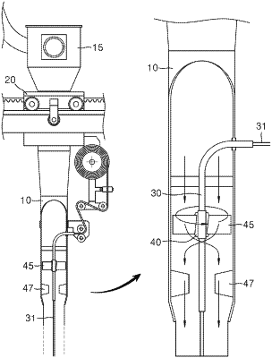
1. A nozzle of a reinforcement material co-printing type 3D printer for construction, wherein in a nozzle (10) of 3D printer for construction, a main pipe (30) parallel to the nozzle (10) is embedded in the nozzle (10), the main pipe (30) being a hollow pipe body having a transfer hole (33) formed in an axial direction therein;
an exposed pipe (36) as a pipe body having the transfer hole (33) formed in an axial direction therein and exposed outside the nozzle (10) is formed;
the other end of the main pipe (30) at a distal end of the nozzle (10) is connected to the exposed pipe (36) via a curved pipe (34), such that as a filament material (31) introduced into the transfer hole (33) of the exposed pipe (36) is discharged from an end of the main pipe (30) at the distal end of the nozzle (10) via the main pipe (30), the filament material (31) may be co-printed with a printing material while embedded in the printing material;
a rotable body (40) is mounted on the main pipe (30) and configured to be freely rotatable about the main pipe (30) without an additional power;
on an outer circumferential surface of the rotable body (40), a plurality of agitating blades (45) inclined relative to the main pipe (30) are radially formed around the main pipe (30), such that discharging of a fluid printing material via the nozzle (10) brings the agitating blades (45) and the rotable body (40) into rotation around the main pipe (30); and
on an inner circumferential surface of the nozzle (10) between the agitating blades (45) and a distal end of the nozzle (10), a plurality of fixed blades (47) parallel to a central axis of the nozzle (10) are radially formed around the central axis of the nozzle (10),
wherein the fixed blades (47) are configured to realign the fluid printing material primarily agitated by the agitating blades (45) while passing therethrough without material segregation.
|