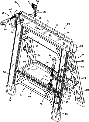
| CPC B25H 1/06 (2013.01) | 14 Claims |

|
1. A hybrid clamp comprising:
a clamp bar;
a first clamp element comprising a first clamp body having a first cylindrical mounting portion, said first mounting portion having at least one first slot extending perpendicularly therethrough for receiving said clamp bar, a first clamp member connected to said first clamp body, said first clamp member comprising at least one adjustable member, and said first clamp element defining a first extension, whereby said first extension and said first mounting portion are a unitary component such that said first extension is fixed with respect to said first mounting portion;
a second clamp element comprising a second clamp body having a second cylindrical mounting portion, said second mounting portion having at least one second slot extending perpendicularly therethrough for receiving said clamp bar, a second clamp member connected to said second clamp body, said second clamp member comprising a stop, and said second clamp element defining a second extension, whereby said second extension and said second mounting portion are a unitary component such that said second extension is fixed with respect to said second mounting portion;
whereby said first and second clamp bodies are configured to be movably located on said clamp bar with said clamp bar extending through said first slot and said second slot, permitting said associated first and second clamp members to clamp an element therebetween, and whereby said first and second clamp bodies are configured to be connected to a support independently of said clamp bar by location of each of said first and second cylindrical mounting portions into a corresponding cylindrical aperture in said support, wherein said first extension of said first clamp element is engageable with a portion of said support to prevent rotation of said first clamp element with respect to said support and said second extension is engageable with a portion of said support to prevent rotation of said second clamp element with respect to said support.
|