| CPC B25F 5/02 (2013.01) [B23D 51/16 (2013.01); B25F 3/00 (2013.01)] | 18 Claims |

|
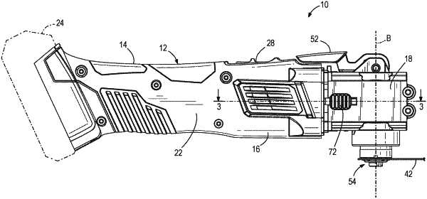
1. An oscillating power tool comprising:
a housing;
a motor disposed generally within the housing, the motor including a drive shaft rotatable about a motor axis;
an output spindle configured to be driven by the motor and journaled for oscillating rotation about an oscillation axis;
a drive mechanism configured to convert rotation of the drive shaft into oscillating rotation of the output spindle about the oscillation axis, the drive mechanism including an eccentric member configured to rotate off center about the motor axis, and a forked member operatively coupled to the eccentric member and configured for oscillating rotation about the oscillation axis in response to rotation of the eccentric member,
wherein oscillating rotation of the forked member has an angular amplitude about the oscillation axis, wherein the eccentric member is movable in a direction generally parallel to the motor axis to change the angular amplitude of oscillating rotation of the forked member, wherein the eccentric member includes a front surface and a rear surface opposite the front surface, wherein the front surface is closer to the output spindle than the rear surface, wherein the rear surface is closer to the motor than the front surface, wherein a set of three orthogonal reference planes intersect each other at a geometric center of the eccentric member, the set of three orthogonal reference planes including first and second planes defining four substantially equal quadrants on the front and rear surfaces of the eccentric member and a third plane separating the front surface from the rear surface; and
an amplitude adjustment actuator configured to move the eccentric member in the direction generally parallel to the motor axis to change the angular amplitude of oscillating rotation of the forked member, wherein the amplitude adjustment actuator is configured to engage the eccentric member on the front surface and on the rear surface, wherein the amplitude adjustment actuator is configured to engage the eccentric member on both sides of the first plane, wherein the amplitude adjustment actuator is configured to engage the eccentric member on both sides of the second plane, wherein the amplitude adjustment actuator comprises a first actuator portion configured to engage the eccentric member on a first side of the first plane and a second actuator portion configured to engage the eccentric member on a second side of the first plane, wherein the first and second actuator portions are formed as separate pieces, and wherein the first portion includes a first actuation surface extending through a first aperture in the housing and the second portion includes a second actuation surface extending through a second aperture in the housing.
|