| CPC B22D 41/56 (2013.01) [B22D 41/14 (2013.01); B22D 41/24 (2013.01); B22D 41/26 (2013.01); B22D 41/44 (2013.01); B22D 41/48 (2013.01)] | 5 Claims |

|
1. A steel ladle drainage method using a steel ladle structure, wherein:
the steel ladle structure comprises:
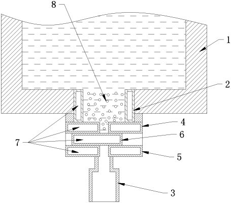
a ladle body, wherein a ladle nozzle is provided at a bottom of the ladle body; and
an opening and closing device installed on the ladle nozzle for separating the ladle nozzle into an upper nozzle and a lower nozzle, wherein:
the opening and closing device comprises an upper fixed plate connected with a bottom portion of the upper nozzle and a lower fixed plate connected with a top portion of the lower nozzle;
the upper and lower fixed plates have two pouring holes respectively, a sliding plate is movably arranged between the upper and lower fixed plates for plugging or connecting the two pouring holes, vacuum interlayers are provided within the upper nozzle, the upper and lower fixed plates and the sliding plate respectively;
the steel ladle drainage method comprises steps of:
(S1) plugging the two pouring holes of the upper and lower fixed plates by moving the sliding plate, and baking the ladle body;
(S2) introducing a metal drainage agent into the ladle body, and then adding liquid steel into the ladle body, melting the metal drainage agent by the added liquid steel, and depositing the melted metal drainage agent in the upper nozzle;
(S3) refining the ladle body in an LF (ladle furnace) and a RH furnace; and
(S4) connecting the two pouring holes of the upper and lower fixed plates by moving the sliding plate, and the metal drainage agent entering a tundish through the two pouring holes and the lower nozzle under an action of gravity for draining the liquid steel, wherein the step of (S2), the metal drainage agent is lead, lead-bismuth alloy or lead-antimony alloy.
|