| CPC A61L 2/10 (2013.01) [C02F 1/325 (2013.01); C02F 2201/003 (2013.01); C02F 2201/3222 (2013.01); C02F 2201/3227 (2013.01); C02F 2201/3228 (2013.01); C02F 2303/04 (2013.01)] | 14 Claims |

|
1. A sterilizing device for sterilizing a fluid, comprising:
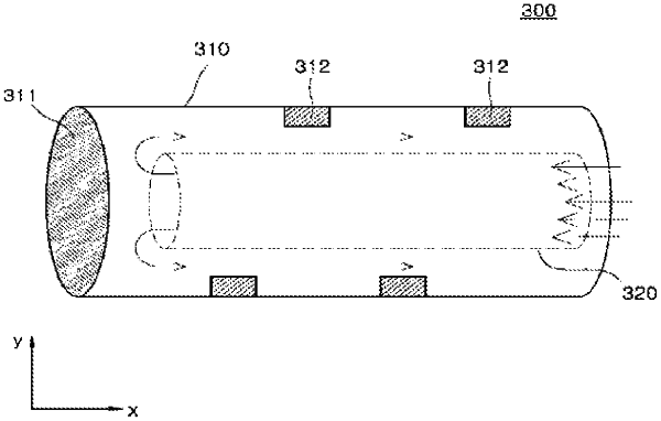
a first pipe having a closed region and an open region that are disposed at opposite sides of the first pipe, the open region of the first pipe configured to allow a fluid to enter the sterilizing device for sterilization;
a second pipe disposed inside the first pipe and having an open region spaced apart from the closed region of the first pipe;
a light reflector disposed on the first pipe and configured to prevent occurrence of a non-irradiation region of ultraviolet (UV) light within the second pipe; and
a first UV light emitting diode (LED) and a second UV LED that are disposed on the first pipe and configured to irradiate the UV light onto the fluid;
wherein one of the first UV LED and the second UV LED is positioned within a beam angle of the UV light emitted by the other of the first UV LED and the second UV LED, and
wherein the closed region of the first pipe is structured to allow the fluid to change a direction of a flow from a first direction to a second direction and the first pipe and the second pipe are configured to increase irradiation time of the UV light per unit volume for the fluid as compared to a case having only one pipe.
|