| CPC A61H 1/024 (2013.01) [A61H 1/00 (2013.01); A61H 2201/0134 (2013.01); A61H 2201/0149 (2013.01); A61H 2201/0192 (2013.01); A61H 2201/1207 (2013.01); A61H 2201/123 (2013.01); A61H 2201/1238 (2013.01); A61H 2201/1246 (2013.01); A61H 2201/1253 (2013.01); A61H 2201/1623 (2013.01); A61H 2201/1628 (2013.01); A61H 2201/164 (2013.01); A61H 2201/1642 (2013.01); A61H 2201/1676 (2013.01); A61H 2201/5023 (2013.01); A61H 2201/5056 (2013.01); A61H 2201/5069 (2013.01); A61H 2203/0431 (2013.01); A61H 2203/0456 (2013.01); A61H 2205/102 (2013.01)] | 17 Claims |
|
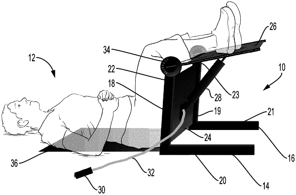
1. An apparatus for use in a treatment to assist with joint range of motion therapy of one or more knees of a patient, the apparatus comprising:
a first substantially L-shaped frame and a second substantially L-shaped frame, each L-shaped frame having a first member and a second member, the first member extending from the second member in a single direction at an angle that is fixed and substantially perpendicular to the second member and terminating in a first end, wherein the first member has a length that generally corresponds to that of a portion the patient's one or more legs from about the hips of the patient to above the one or more knees of the patient;
a fixed plate extending between and coupled to the first members of the first and second substantially L-shaped frames, the fixed plate being parallel with the first members of the first and second substantially L-shaped frames;
a movable plate pivotally coupled to and having an axis of rotation passing through the first ends of the first members of the first and second substantially L-shaped frames, wherein the movable plate is configured to support one or more legs below the one or more knees without securing the patient to the apparatus and to rotate relative to the first and second substantially L-shaped frames and the fixed plate thereby allowing knee flexion aligned with the axis of rotation of the movable plate;
a pneumatic piston pivotally coupled to the movable plate and pivotally coupled to the fixed plate, the pneumatic piston adapted and configured to control an angle between the movable plate and the fixed plate;
a hand operated valve operatively coupled to the pneumatic piston, the hand operated valve adapted and configured to control the flow of air into and out from the pneumatic piston such that movement of the movable plate relative to the fixed plate can be allowed and prevented by operation of the hand operated valve; and
a goniometer coupled to the movable plate and one of the first and second substantially L-shaped frames, the goniometer adapted and configured to indicate the angle between the movable plate and the fixed plate.
|