| CPC A61B 18/1485 (2013.01) [A61B 18/14 (2013.01); A61B 34/10 (2016.02); A61B 34/20 (2016.02); A61N 1/0546 (2013.01); A61N 1/403 (2013.01); G06T 7/0012 (2013.01); A61B 2017/00199 (2013.01); A61B 2017/00292 (2013.01); A61B 2017/00424 (2013.01); A61B 2017/00867 (2013.01); A61B 2018/0016 (2013.01); A61B 2018/00166 (2013.01); A61B 2018/00214 (2013.01); A61B 2018/00303 (2013.01); A61B 2018/00327 (2013.01); A61B 2018/00434 (2013.01); A61B 2018/00577 (2013.01); A61B 2018/00654 (2013.01); A61B 2018/00815 (2013.01); A61B 2018/00821 (2013.01); A61B 2018/00875 (2013.01); A61B 2018/00922 (2013.01); A61B 2018/00946 (2013.01); A61B 18/02 (2013.01); A61B 18/1206 (2013.01); A61B 2018/1253 (2013.01); A61B 2018/126 (2013.01); A61B 2018/1407 (2013.01); A61B 2018/144 (2013.01); A61B 2018/1467 (2013.01); A61B 2018/1475 (2013.01); A61B 2018/1823 (2013.01); A61B 18/20 (2013.01); A61B 2034/102 (2016.02); A61B 2090/3735 (2016.02); A61B 2090/3762 (2016.02); A61B 2090/378 (2016.02); A61B 90/94 (2016.02); A61B 2218/007 (2013.01)] | 20 Claims |

|
1. A device for treating a condition within a nasal cavity of a patient, the device comprising:
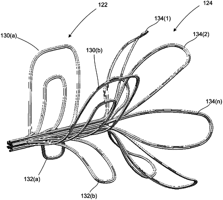
a multi-segment end effector operably associated with a shaft and comprising a first segment that is spaced apart from a separate and distinct second segment along a longitudinal axis along which a distal most portion of the shaft lies, wherein the second segment is positioned closer to a distal-most end of the shaft and the first segment is positioned closer to a proximal-most end of the shaft, each of the first and second segments is transformable between a retracted configuration and an expanded deployed configuration and comprises a respective architecture in the expanded deployed configuration, the first segment comprises a first architecture and the second segment comprises a second architecture that is different than the first architecture of the first segment,
wherein the first segment comprises:
a first set of a plurality of flexible support elements that extend in a first outward direction relative to the longitudinal axis and are positioned within a first half of the first segment and cooperatively form an inwardly extending first concave shape when the first segment is in the expanded deployed configuration; and
a second set of a plurality of flexible support elements that extend in a second outward direction relative to the longitudinal axis and substantially opposite the first outward direction and are positioned within a second half of the first segment and cooperatively form an inwardly extending second concave shape substantially mirroring the first concave shape when the first segment is in the expanded deployed configuration, the first and second sets of plurality of flexible support elements cooperatively define the first architecture of the first segment when in the expanded deployed configuration, and
wherein the second segment comprises a third set of flexible support elements that cooperatively form the second segment and define the second architecture of the second segment when in the expanded deployed configuration, wherein each flexible support element of the first, second, and third sets comprises one or more electrodes provided thereon; and
a handle operably associated with the shaft, the handle having a first user-manipulatable mechanism for deployment of each of the first and second segments of the multi-segment end effector from the retracted configuration to the expanded deployed configuration and a second user-manipulatable mechanism, separate from the first user-manipulatable mechanism, for control of energy output by each of the first, second, and third segments of the multi-segment end effector.
|