| CPC A47J 36/2483 (2013.01) [B65G 15/34 (2013.01); B65G 23/04 (2013.01); B65G 23/44 (2013.01); H05B 1/0263 (2013.01); H05B 3/26 (2013.01); B65G 2203/0291 (2013.01)] | 14 Claims |

|
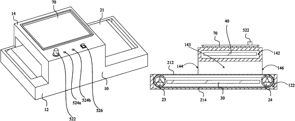
1. A food heating apparatus comprising:
a housing;
a conveyor assembly;
a first heating element;
a second heating element;
a control unit;
a power source;
the housing comprising a base portion and a top portion;
the base portion forming a first interior space in which the conveyor assembly is located;
the top portion forming a second interior space in which the second heating element is located;
the top portion further forming a tunnel;
the tunnel comprising an entrance and an exit;
the conveyor assembly comprising a belt, a motor, a driving pulley, a driven pulley, and a tensioning mechanism;
the belt comprising an upper food-carrying run and a lower return run;
the driving pulley comprising a first cylindrical body and a driving pulley shaft;
the driven pulley comprising a second cylindrical body that is substantially of the same diameter as the first cylindrical body and a driven pulley shaft;
the motor being electrically connected to the power source and comprising an output shaft which is connected to the driving pulley shaft;
the tensioning mechanism comprising a first tensioning assembly and a second tensioning assembly;
the first tensioning assembly and the second tensioning assembly being arranged on opposite ends of the driven pulley shaft, respectively;
each of the first tensioning assembly and the second tensioning assembly comprising a frame, a movable block, and a spring;
the frame of each of the first tensioning assembly and the second tensioning assembly comprising a groove with an expanded section and a reduced section;
the movable block of each of the first tensioning assembly and the second tensioning assembly moving linearly in respective expanded section;
the movable block of each of the first tensioning assembly and the second tensioning assembly comprising a hole to receive an end of the driven pulley shaft, respectively;
the spring of each of the first tensioning assembly and the second tensioning assembly being, at one end, connected to respective movable block;
the spring of each of the first tensioning assembly and the second tensioning assembly being, at an opposite end, engaging an end wall of the reduced section; and
the control unit comprising a control circuit that is configured to control a speed of the motor.
|