| CPC H02M 7/487 (2013.01) [H02M 1/14 (2013.01); H02M 7/23 (2013.01); H02M 7/483 (2013.01); H02M 7/49 (2013.01); H02M 7/5387 (2013.01)] | 20 Claims |

|
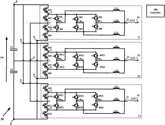
1. An apparatus comprising:
a pair of input terminals configured to supply a direct current (DC) voltage;
a first series connection comprising a first capacitor and a second capacitor, wherein the first series connection is connected across the pair of input terminals, and the first capacitor is connected to the second capacitor at a first terminal;
a controller; and
a plurality of power converters, wherein each power converter of the plurality of power converters is coupled to the pair of input terminals and configured to convert the DC voltage to an alternating-current (AC) voltage at a first output frequency at a respective output terminal;
wherein each power converter of the plurality of power converters comprises:
a second series connection comprising a first switch, a second switch, a third switch and a fourth switch, wherein the second series connection is connected across the pair of input terminals, wherein the first switch is connected to the second switch at a second terminal, wherein the second switch is connected to the third switch at a third terminal, wherein the third switch is connected to the fourth switch at a fourth terminal; and
a plurality of circuits, wherein each circuit of the plurality of circuits comprises:
an additional series connection comprising two or more switches across the second terminal and the fourth terminal and an intermediate node between the two or more switches of the additional series connection; and
a first leg comprising an inductor having mutual inductance with another inductor of a second leg, wherein the first leg is connected between the intermediate node and an output terminal; and
wherein the controller is configured to control, based on one or more current measurements for a first inductor of a first circuit of the plurality of circuits or a second inductor of a second circuit of the plurality of circuits, a first current of the first inductor or a second current of the second inductor to balance the first current with the second current.
|