| CPC H02M 3/073 (2013.01) [H02M 3/155 (2013.01)] | 1 Claim |

|
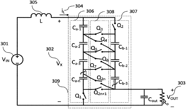
1. A step down converter driving a load comprising in combination:
a voltage source having a first terminal and a second terminal;
a first series connection of first multiple capacitors connected in series with a first switch, the first switch connected to the first terminal of the voltage source;
a second series connection of second multiple capacitors connected in series with a second switch, wherein an end of the second multiple capacitors is connected to the first terminal of the voltage source;
an inductor having a first inductor terminal and a second inductor terminal, wherein:
the first inductor terminal is connected to the second terminal of the voltage source, and
the second inductor terminal is connected to a first capacitor of the first series connection of the first multiple capacitors and the first switch, and the second terminal of the inductor is also connected to the second series connection of the second multiple capacitors and the second switch;
third multiple switches each having a first switch terminal and a second switch terminal;
the first switch terminal of each of the third multiple switches connected to first common nodes of the first series connection of the first multiple capacitors and the first switch, the second switch terminal of each of the third multiple switches connected to second common nodes of the second series connection of the second multiple capacitors and the second switch and each of the third multiple switches positioned between the first common nodes or the second common nodes connecting either the same order of first common nodes of the first series connection of the first multiple capacitors and the first switch and second common nodes the second series connection of the second multiple capacitors and the second switch, or (N)th common nodes of the first series connection of the first multiple capacitors and the first switch and (N+1)th common node of the second series connection of the second multiple capacitors and the second switch; and
a load connected in parallel to a last capacitor of the second series connection of the second multiple capacitors and the second switch.
|