| CPC H02K 5/24 (2013.01) [H02K 2213/03 (2013.01)] | 2 Claims |

|
1. A motor case that accommodates a stator, a rotor facing an inner periphery of the stator, and a rotating shaft coupled to the rotor, the motor case comprising:
a peripheral wall which is formed in a tubular shape and has a space accommodating the stator and the rotating shaft on an inside;
a flange portion which is formed at one end of the peripheral wall and is coupled to an outside;
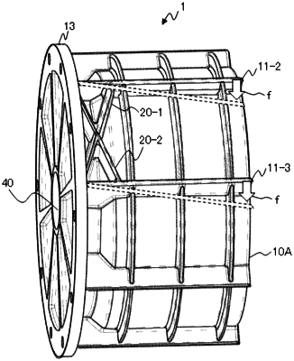
damping ribs which are formed at an outer periphery of the peripheral wall, are formed between (i) a position crossing the outer periphery of the peripheral wall and (ii) the flange portion on an extension of the rotating shaft in a radial direction from an end portion of the stator; and
at least two linear ribs which are formed on the outer periphery of the peripheral wall in a direction parallel to an axial direction of the rotating shaft,
wherein the damping ribs (i) are formed between the at least two linear ribs, (ii) cross each other, and (iii) connect the linear ribs and the flange portion to each other.
|