| CPC H02K 41/03 (2013.01) [H02K 11/0141 (2020.08)] | 4 Claims |

|
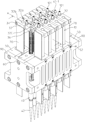
1. A multi-axis linear motor actuator comprising a plurality of linear shaft motors arranged in a row at a predetermined pitch, the linear shaft motors each comprising a magnet portion for the linear shaft motor and a coil portion for the linear shaft motor, the magnet portion including a plurality of permanent magnets which are connected to each other with the same magnetic poles faced to each other and which are fixed to a support member having a length equal to or longer than a total length of the plurality of permanent magnets connected to each other to form a shaft movable in an axial direction, the coil portion including a plurality of cylindrical coils connected to each other in a center axis direction and combined with the shaft to concentrically enclose the shaft via a gap so that the shaft is movable with respect to the axial direction, the multi-axis linear motor actuator including:
a circuit board which has a size sufficient to cover a plurality of the coil portions in the plurality of linear shaft motors arranged in a row and which is combined with the plurality of linear shaft motors so as to be adjacent thereto and parallel to an arrangement direction of the plurality of linear shaft motors; and
a plurality of magnetic shielding plates, longer than the coil portion, each arranged and fixed along the axial direction at least at a position corresponding to a position between adjacent ones of the plurality of coil portions arranged in a row; and
a pair of Hall sensors installed in the circuit board in each of regions corresponding to the shafts, same in number as the plurality of linear shaft motors, at intervals in a moving direction of the shaft;
each of the magnetic shielding plates having a wide portion with a width greater than a diameter of the coil portion at least at a part corresponding to the region where the pair of Hall sensors are installed;
the circuit board being provided with a plurality of first slits each for inserting the wide portion;
the pair of Hall sensors being installed adjacent to the wide portion of the magnetic shielding plate.
|