| CPC H02K 1/17 (2013.01) [H02K 3/28 (2013.01); H02K 15/12 (2013.01)] | 7 Claims |

|
1. An electric motor comprising:
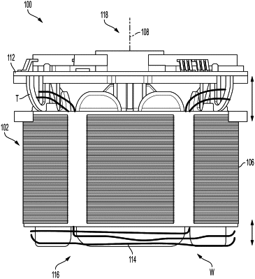
a stator assembly including
a lamination stack,
a printed circuit board assembly (PCBA) coupled to the lamination stack at an axial end of the stator assembly,
a plurality of windings wrapped about the lamination stack to form a plurality of coils, the plurality of windings comprising a first winding defining a first coil of the plurality of coils and a second coil of the plurality of coils located opposite from the first coil, and
a plurality of terminals configured to electrically connect the plurality of windings to the PCBA, the plurality of terminals comprising a first terminal and a second terminal;
wherein the first coil and the second coil are connected in parallel between the first terminal and the second terminal; and
wherein the PCBA is configured to supply a current to the first coil and the second coil.
|