| CPC H01R 4/48365 (2023.08) [H01R 4/48455 (2023.08); H01R 11/05 (2013.01); H01R 13/113 (2013.01); H01R 13/502 (2013.01); H01R 24/22 (2013.01); H01R 24/30 (2013.01)] | 22 Claims |

|
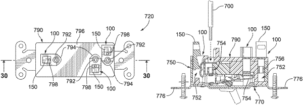
1. An electrical switch comprising:
a housing having a main body portion, a front cover portion and a rear cover portion, the main body portion having a plurality of cavities, the front cover portion being removably secured to a first side of the main body portion and having a switch arm aperture through which at least a portion of a toggle switch can pass, and the rear cover portion being removably secured to a second side of the main body portion and having a plurality of wire receiving apertures and a plurality of plunger openings;
a plurality of switch contacts, wherein one of the plurality of switch contacts is positioned within one of the plurality of cavities;
a plurality of contact assemblies, wherein one of the plurality of contact assemblies is electrically connected to one of the plurality of switch contacts;
wherein one of the plurality of contact assemblies is positioned at least partially within one of the plurality of cavities and is accessible from one of the plurality of wire receiving apertures and one of the plurality of plunger openings in the rear cover portion; and
wherein each of the plurality of the contact assemblies includes:
a wire terminal forming an electrically conductive path between the contact assembly and an electrical wire inserted into one of the plurality of wire receiving apertures, the wire terminal including a clamp brace and a clamp spring secured to the clamp brace, the clamp spring being movable relative to the clamp brace between a closed position where the electrical wire can be clamped between the clamp spring and the clamp brace with a force that is substantially perpendicular to a longitudinal axis of the electrical wire so that the clamp spring can compress the electrical wire against the clamp brace, and an open position where the electrical wire can be inserted through the one of the plurality of wire receiving apertures and between the clamp spring and the clamp brace; and
a plunger positioned within one of the plurality of cavities and extending at least partially through one of the plurality of plunger openings in the rear cover, the plunger being interactive with the clamp spring such that movement of the plunger in a first direction causes the plunger to apply a mechanical load to the clamp spring to cause the clamp spring to move from the closed position to the open position and movement of the plunger in a second direction removes the mechanical load from the clamp spring so that to the clamp spring is biased from the open position to the closed position.
|