| CPC G02B 6/38875 (2021.05) [G02B 6/3825 (2013.01); G02B 6/387 (2013.01); G02B 6/3879 (2013.01); G02B 6/3887 (2013.01); G02B 6/3893 (2013.01); G02B 6/403 (2013.01); G02B 6/406 (2013.01); G02B 6/4292 (2013.01); G02B 6/3821 (2013.01)] | 20 Claims |

|
1. An optical fiber connector for terminating a cable comprising a jacket surrounding a plurality of optical fibers, the optical fiber connector comprising:
at least one ferrule configured for terminating one or more optical fibers;
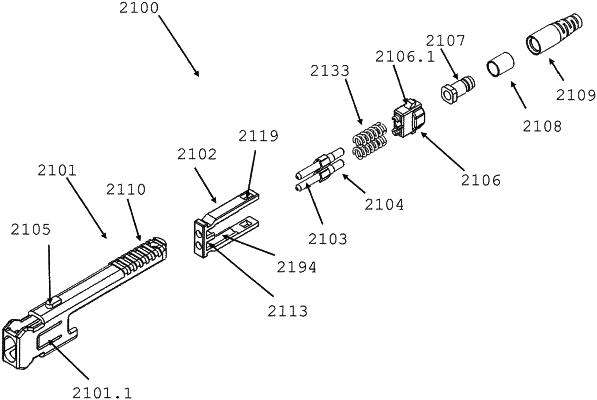
a connector housing assembly including a front body and a back body holding the at least one ferrule such that the at least one ferrule extends forward along a longitudinal axis of the optical fiber connector from the front body; and
a boot assembly having a front end and a rear end spaced apart along the longitudinal axis, the boot assembly comprising a boot defining the rear end of the boot assembly and an alignment key defining the front end of the boot assembly, the boot assembly configured to couple to the connector housing assembly such that the boot extends rearward of the connector housing assembly for surrounding the jacket of the cable and the alignment key is disposed on one side of the connector housing assembly,
wherein the optical fiber connector is configured to mate with an adapter having a keyway along a first wall of the adapter, the alignment key configured to be slidably received in the keyway as the optical fiber connector is mated with the adapter, and
wherein the optical fiber connector is configured to latch with the adapter when mated with the adapter, the boot assembly configured to be displaced rearward in relation to the front body and the back body to actuate the optical fiber connector to unlatch from the adapter.
|