| CPC G01S 7/4817 (2013.01) [G01S 7/4813 (2013.01); G01S 7/4815 (2013.01); G01S 17/08 (2013.01); G01S 17/931 (2020.01); G02B 26/105 (2013.01)] | 9 Claims |

|
1. A lidar device comprising:
a light detection module disposed in a housing that has an opening, the light detection module being configured to:
transmit a transmitted light beam in a transmission direction to scan the transmitted light beam in a scanning direction, the transmission direction being predetermined and the scanning direction being predetermined; and
receive a reflected light beam arriving from a scanning region of the transmitted light beam; and
an optical window attached to the opening of the housing and curved toward an outside of the housing, the optical window having:
a window center in the scanning direction;
an outer side surface facing the outside of the housing; and
an inner side surface facing an inside of the housing,
the optical window being configured to enable:
the transmitted light beam to pass therethrough; and
the received reflected light beam to pass therethrough;
wherein:
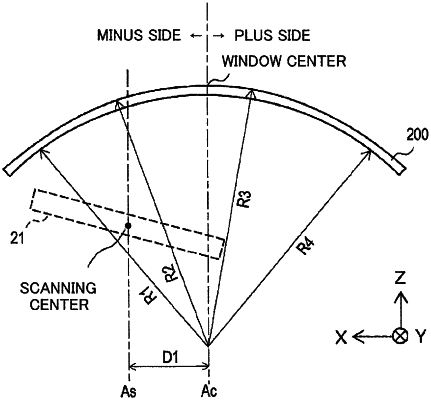
the light detection module is arranged such that a scanning center indicative of a center of the scanning of the light beam is located to be different from the window center in the scanning direction;
the optical window has a target surface that is one of the outer side surface and the inner side surface;
the target surface has a cross-section along a scanning surface of the transmitted light beam, the scanning surface being defined by the scanning direction of the transmitted light beam and the transmission direction of the light beam from the light detection module, the cross-section of the target surface being shaped to be asymmetrical about the window center,
the cross-section of the target surface is configured to have partitioned sections in the scanning direction, the partitioned sections respectively having different radii of curvature;
the light detection module has a light reception device;
the reflected light beam arriving from the scanning region is incident at a position in the light reception device; and
the target surface has a radius of curvature that is determined to cause the position of the reflected light beam at the light reception device to satisfy a predetermined allowable position condition.
|