| CPC G01R 1/07357 (2013.01) [G01R 1/06711 (2013.01)] | 9 Claims |
|
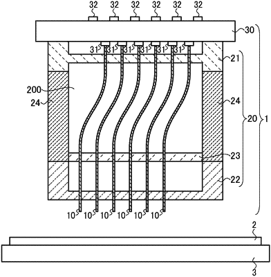
1. An electrical connecting device used for measuring an electrical characteristic of an inspection object, the device comprising:
a probe having a tip end part brought into contact with the inspection object during measurement of the inspection object; and
a probe head including a top guide plate through which a region adjacent to a proximal end part of the probe penetrates, a bottom guide plate through which a region adjacent to the tip end part of the probe and away from the top guide plate penetrates, and a middle guide plate through which the probe penetrates, the middle guide plate being arranged between the top guide plate and the bottom guide plate and closer to the bottom guide plate,
wherein the top guide plate and the middle guide plate are provided with guide holes through which the probe is inserted at positions shifted between the top guide plate and the middle guide plate as viewed in a surface normal direction of a main surface of the top guide plate so as to lead the probe to be held in a bent state between the top guide plate and the middle guide plate,
wherein the probe bends into a buckled state when the tip end part is brought into contact with the inspection object, the buckled state associated with buckling at a maximum stress region of the probe, and the maximum stress region located between the top guide plate and the middle guide plate, and
the probe has a structure located at a bend region other than the maximum stress region, wherein the probe is easier to bend at the bend region than at the maximum stress region when the tip end part is brought into contact with the inspection object, the maximum stress region being defined at a position at which a maximum stress is applied to the probe when buckled due to the contact of the tip end part with the inspection object.
|