| CPC F25B 41/42 (2021.01) [F28F 9/0246 (2013.01); F28F 9/026 (2013.01); F25B 2339/00 (2013.01); F25B 2500/09 (2013.01)] | 13 Claims |

|
1. An outdoor unit comprising:
a fan configured to send an outdoor air; and
a heat exchanger that operates as an evaporator configured to cause heat exchange to be performed between refrigerant being in a two-phase gas-liquid state and the outdoor air to evaporate the refrigerant,
wherein the heat exchanger includes
a plurality of heat transfer tubes,
a liquid header distributor to which one end of each of the plurality of heat transfer tubes is connected and in which an upward flow of the refrigerant being in the two-phase gas-liquid state is generated, the liquid header distributor being configured to distribute the refrigerant being in the two-phase gas-liquid state to the plurality of heat transfer tubes, and
a gas header distributor to which an other end of each of the plurality of heat transfer tubes is connected, in which the refrigerant being in a gas-phase state is collected, the refrigerant being in the gas-phase state being refrigerant into which the refrigerant being in the two-phase gas-liquid state evaporates in the plurality of heat transfer tubes to change, and in which a flow of gas phase refrigerant is generated,
wherein the plurality of heat transfer tubes include respective U-shaped bent portions at each of which a flow passage is bent,
wherein the heat exchanger further includes a heat exchanger core that includes the plurality of heat transfer tubes and one or more fins,
wherein in the heat exchanger core, of the plurality of heat transfer tubes, at least one heat transfer tube located at an upper portion of the liquid header distributor includes a larger number of U-shaped bent portions than at least one heat transfer tube located at a lower portion of the liquid header distributor,
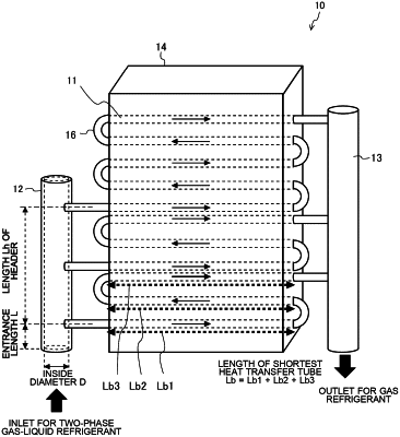
wherein a relationship between the liquid header distributor and the plurality of heat transfer tubes is established such that 9≤ζ is satisfied, where Lh [m] is a length of the liquid header distributor that corresponds to a distance between a central axis of one of the plurality of heat transfer tubes that is the closest to an inlet of the liquid header distributor and a central axis of one of the plurality of heat transfer tubes that is the farthest from the inlet of the liquid header distributor, Lb [m] is a length of a shortest one of the plurality of heat transfer tubes, the length Lb of the shortest one of the plurality of heat transfer tubes corresponding to a distance by which the shortest one of the plurality of heat transfer tubes, which extends from the liquid header distributor to the gas header distributor through the heat exchanger core and the U-shaped bent portions, extends through the heat exchanger core, and ζ is a ratio of the length Lb of the shortest one of the plurality of heat transfer tubes to the length Lh of the liquid header distributor and is expressed by ζ=Lb/Lh,
the outdoor unit having a top-flow housing in which an air velocity is higher at the upper portion of the liquid header distributor than that at the lower portion of the liquid header distributor, the upper portion of the liquid header distributor being relatively close to the fan, and
wherein the at least one heat transfer tube including the larger number of U-shaped bent portions is located at the upper portion of the liquid header portion and the air velocity at the upper portion of the liquid header portion is higher than that at the lower portion of the liquid header distributor.
|