| CPC F24F 1/0022 (2013.01) [F04D 29/30 (2013.01); F04D 29/422 (2013.01); F04D 29/4226 (2013.01)] | 5 Claims |

|
1. An air-conditioning apparatus comprising:
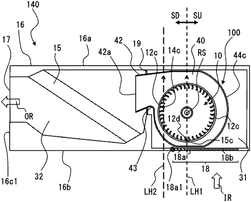
a centrifugal air-sending device including a fan and a scroll casing, the fan including a main plate that is driven to rotate and a plurality of blades provided at a circumferential edge portion of the main plate, the scroll casing accommodating the fan and including a circumferential wall and a side wall, the circumferential wall being formed in the shape of a scroll, the side wall having a suction port that communicates with a space defined by the main plate and the plurality of blades;
a heat exchanger through which an air current generated from the centrifugal air-sending device passes; and
a housing that houses the centrifugal air-sending device and the heat exchanger, and has a housing suction port through which air is sucked into the centrifugal air-sending device and a housing air outlet through which air that is sent from the centrifugal air-sending device and passes through the heat exchange flows out from the housing,
wherein the scroll casing has: a tongue portion located at a position from which the circumferential wall extends to be formed in the shape of the scroll, the tongue portion being configured to divide a flow of air blown from the fan; and a discharge portion having a discharge port through which air blown from the fan flows out,
wherein the housing has an opening wall portion having the housing suction port, and the housing suction port is located on a line crossing a direction in which the discharge port extends, and
wherein
where as viewed in a direction along a rotation axis of the fan,
in a radial direction perpendicular to the rotation axis, a trailing edge of one of the plurality of blades that is located closest to a wall portion of the housing is defined as a first trailing edge portion, and a leading edge of one of the plurality of blades that is located closest to the tongue portion is defined as a first leading edge portion,
a straight line that passes through the rotation axis and the first trailing edge portion is defined as a first straight line, and a straight line that is parallel to the first straight line and passes through the first leading edge portion is defined as a second straight line, and
a region that forms part of the housing suction opening that is close to the tongue portion with reference to the rotation axis is defined as a first region,
a boundary portion of the first region that is located closest to the tongue portion is located between the first straight line and the second straight line,
each of the plurality of blades includes
an inner circumferential end located close to the rotation axis in the radial direction,
an outer circumferential end located closer to an outer circumference than the inner circumferential end in the radial direction,
a sirocco blade portion including the outer circumferential end and formed as a forward-swept blade portion having a blade outlet angle of greater than 90 degrees, and
a turbo blade portion including the inner circumferential end and formed as a backward-swept blade portion,
the first leading edge portion is a leading edge of the turbo blade portion, and
the turbo blade portion and the sirocco blade portion are formed integrally with each other.
|