| CPC F24F 1/0011 (2013.01) [F24F 13/08 (2013.01); F24F 13/20 (2013.01)] | 6 Claims |

|
1. An air-conditioning apparatus comprising:
an outer panel having an air inlet and an air outlet;
a fan that forces air to move from the air inlet to the air outlet;
a heat exchanger that exchanges heat with air moved from the air inlet to the air outlet;
a first airflow passage wall located between
a first airflow passage extending from the air inlet to the heat exchanger, and
a second airflow passage extending from the heat exchanger to the air outlet,
the first airflow passage wall extending from between the air inlet and the air outlet of the outer panel to the heat exchanger;
a second airflow passage wall being opposite to the first airflow passage wall;
a third airflow passage wall connected to the first airflow passage wall and the second airflow passage wall, and forms the second airflow passage together with the first airflow passage wall and the second airflow passage wall;
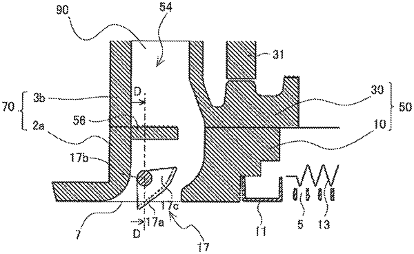
an airflow direction deflector located in the second airflow passage and having a vane and a shaft connected to the vane, the shaft being rotatably supported by the third airflow passage wall,
an airflow speed reducer provided between the heat exchanger and the shaft in the second airflow passage, the airflow speed reducer is disposed to be in an upstream direction from the vane,
wherein
the airflow speed reducer
is directly connected to both the second airflow passage wall and the third airflow passage wall,
protrudes from the second airflow passage wall and the third airflow passage wall,
is spaced apart from the first airflow passage wall, and
is configured to reduce airflow speed such that the airflow moves between the airflow speed reducer and the shaft in the second airflow passage at an airflow speed slower than an airflow speed thereof between the heat exchanger and the airflow speed reducer,
wherein a dimension of the airflow speed reducer in a direction from the second airflow passage wall to the first airflow passage wall is larger than a dimension thereof from the second airflow passage wall to the shaft, and in a direction away from the third airflow passage wall, a position of a front end of the airflow speed reducer is more away from the third airflow passage wall than a position of a front end of the shaft on a vane side is.
|